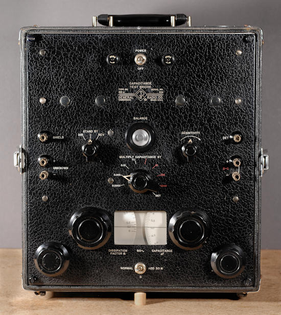

The 1611-A is a handsome instrument, and comes in a portable case with a removable cover and chrome legs on the rear to stand it up. I found mine at a Rochester, NY hamfest one year for $5 or $15, can't remember which. It had a big sign that said "doesn't work", but was in nice shape, so I figured, "what could possibly be wrong with this?". More on that in a minute.
The 1611-A was aimed at both shops and labs. All tests are done at 60 Hz and the range is 0 to 11,000 uF in 8 ranges. Accuracy is 1%. Dissipation range is 0 to 30% on a single log dial, with an additional 30% switched in for a total of 60%. The test voltage can be rather high on small value caps, up to 125 VRMS below 1100 pF. Caution should be used on modern caps, especially multi-layer, that often have low maximum voltage limits. As GR stated in the "L" catalog, "It also meets the requirements of the electric power industry for shop testing of insulators, particularly for measurement of dissipation factor of bushings, insulators, the insulation of transformers, rotating machinery and cables." I think they mentioned insulators twice, but you get the idea. Though the dial is marked down to zero, accuracy at the low end is limited. Divisions are every 2 pF and the bridge is best suited to values above 5 or 10 pF. Like most GR products, it beats its published accuracy specifications by a wide margin.
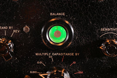
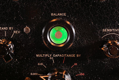
In my opinion, the most interesting feature is the use of a "magic eye" tube as the balance indicator. This is remarkably effective. It can be used in a noisy environment, is not subject to sticking, and has infinite resolution. Shown below is the magic eye in unbalanced and balanced condition. The goal is to get the gap in the display as wide as possible.


So what was wrong with my 1611-A? After a few ohmmeter readings, it became apparent that the multi-section range resistor in one arm was open. It appeared to have been overheated by application of excess voltage, possibly on the DC bias inputs. Though precision wire wound resistors carry some mystique to the uninitiated, they are really quite easy to rebuild. In this case the larger problem was removal of the resistor assembly. It's somewhat buried, and the hardware is nearly impossible to access. After getting the thing out, the open section was rewound with suitable resistance wire. Getting it back in was even harder, and one of the several fastening screws had to be left out, as there was no way to put the nut on the other end. Maybe someday… After repair, the accuracy of the instrument was well within specification.
The later 1611-B incorporated extra jacks to allow an external input of other than 60 Hz and a selectable filter including an external filter jack. It's certainly the more desirable bridge because of that, but either version is a very nice piece for a collection. I've never found a good B version. I still remember lugging this back to the car from the flea market- the published weight is 30 1/2 pounds!
(1/14- Thanks to eBay I picked up an extremely clean example of the 1611-B. It needed the power supply filter cap replaced and had a leaky mica coupling cap, but those items were easily fixed. The eye tube is a bit dimmer than my old A version, but I've got a spare for that if it gets worse. Reading the manual more carefully, it's possible to put a resistor between jacks to reduce the applied voltage for lower voltage and lower capacitance parts- an essential piece of knowledge in the modern low voltage world.)
C. Hoffman
last major edit October 12, 2011