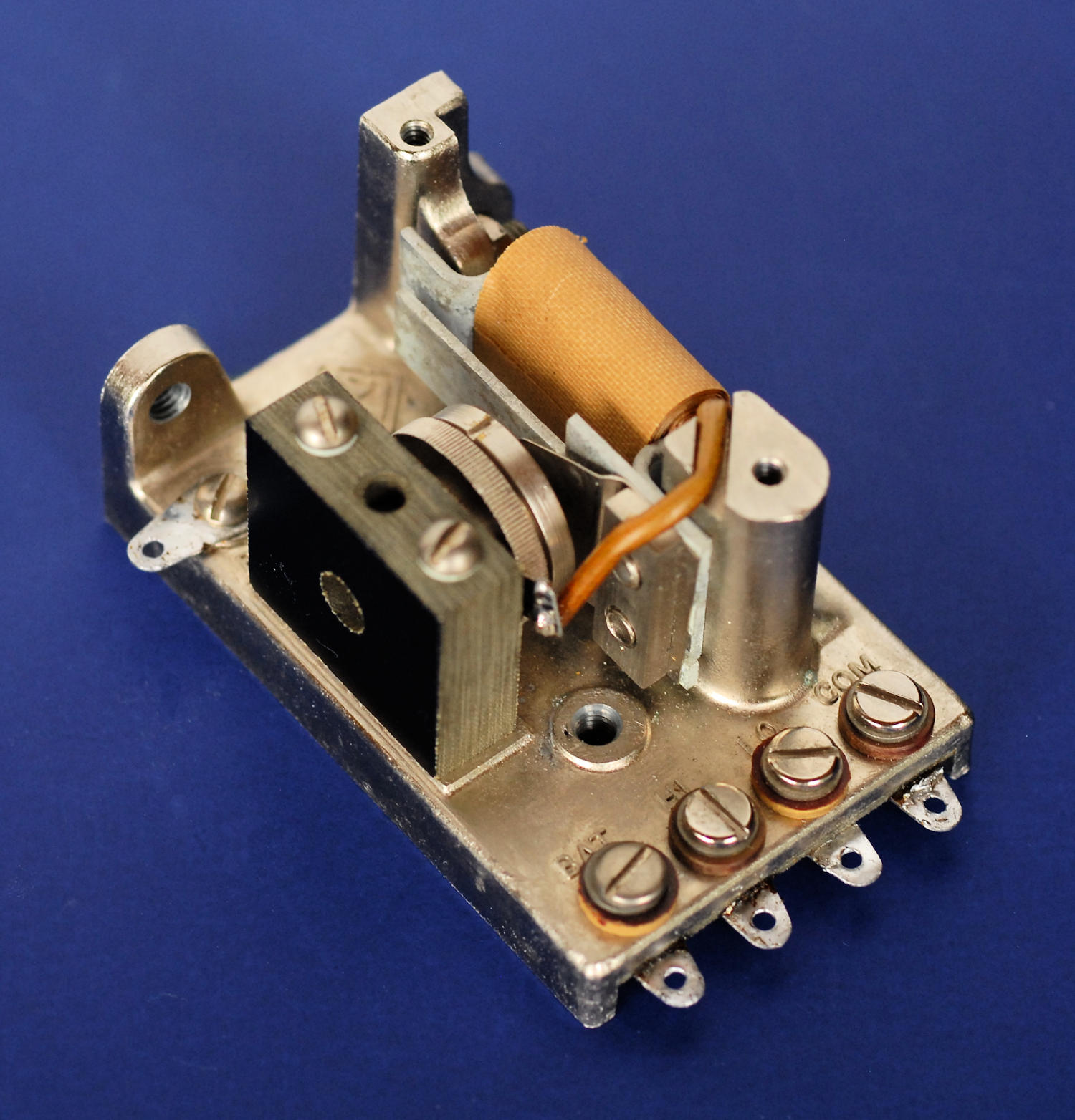

The GR 752-B was a microphone hummer used to generate a 1 kHz sine wave for the 650-A bridge, a Heathkit bridge and for various other purposes. Though fairly common, there is little information on the details of the device. It had no write-up in The General Radio Experimenter and the catalog description is brief. GR also produced a similar device using an actual tuning fork, the 213 oscillator, way back in 1930. There's a write-up of that in the April 1930 issue of The General Radio Experimenter that's useful for understanding the overall operation.
Since information is so scarce, I'm putting up this page with what I know from experimentation on a few 572s. If anybody has more data, or especially the information that might have shipped with the device when it was sold on its own, I'd love to get a copy. Please also tell me if anything here is wrong!
I never thought much about microphone hummers, but they're actually quite fascinating. First, you need to understand carbon microphones. They're just a capsule containing carbon granules trapped between two electrodes. One electrode is also the diaphragm. When sound waves hit the diaphragm, the carbon granules are alternately compressed and released. That changes the resistance through the granules. The phenomena is only a little bit interesting until you realize that a carbon microphone can modulate tens of milliamps of current. You get useful gain without any tubes or transistors. They were used for decades in the plain old telephone system (POTS) that was often powered by batteries in the local exchange.
To build a microphone hummer you need a resonant metal reed or a tuning fork. A small specially designed carbon microphone is attached to the reed or fork. An electromagnet is placed near the reed or fork. Now it's a simple matter to apply a voltage through the microphone, which modulates the current through the electromagnet, vibrating the reed or fork. If the phase is reinforcing, you have an oscillator.
If you can avoid servicing a microphone hummer, do so! The microphone capsules can go bad after a while, and getting the right tensions and clearances is a bit hit and miss. There aren't any instructions from GR on setting these up. I'll tell you what I think I know, but it could be wrong and lead you astray.
Here's a photo of the GR 572-A microphone hummer, with some descriptions added to the parts.
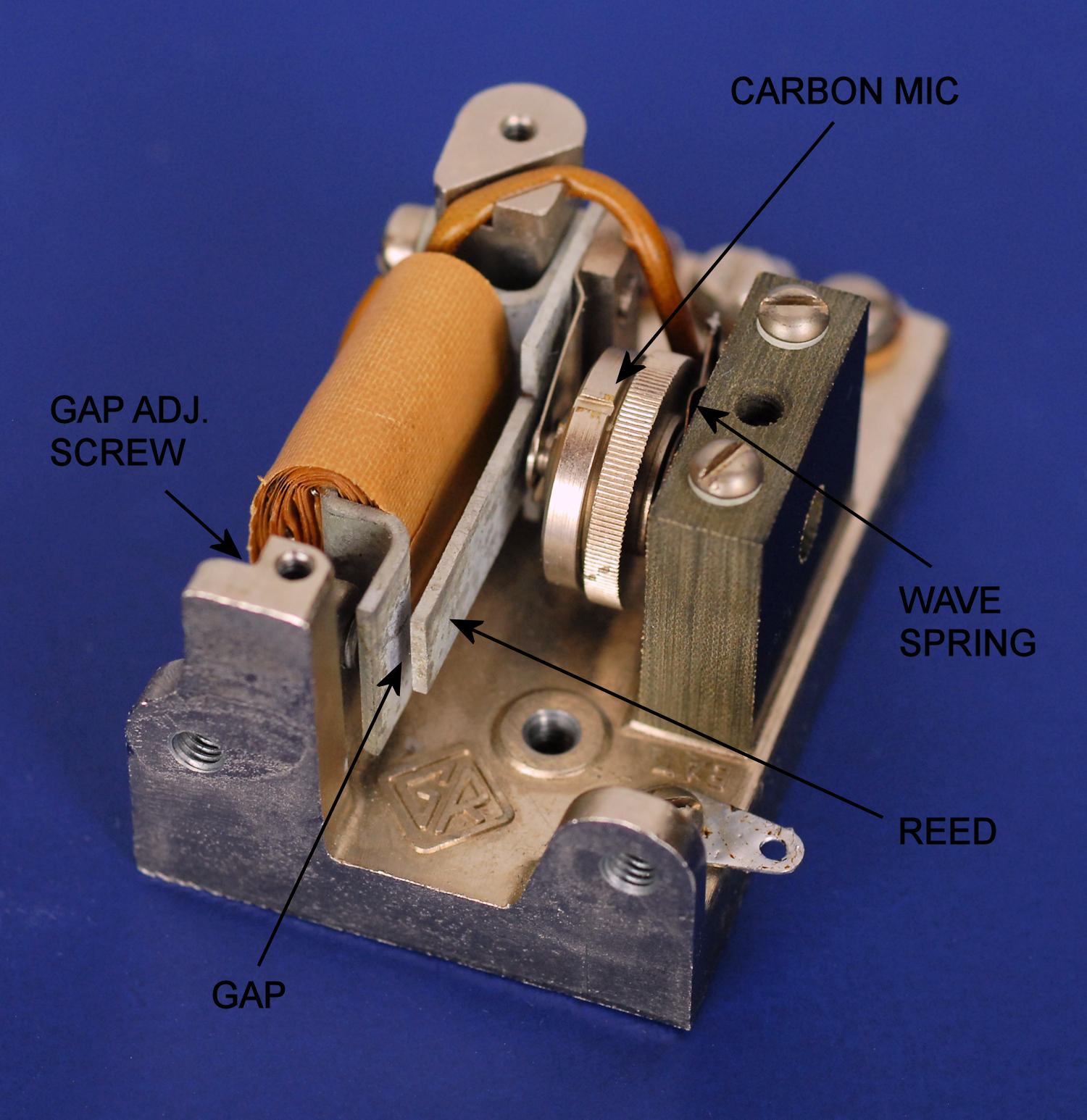
The slotted ring and knurled ring on the microphone capsule are not adjustments! The knurled ring is part of the base that holds the diaphragm and the carbon granules. The slotted ring is the retaining ring that holds it all together. Don't unscrew it unless you've removed the microphone capsule and intend to service it. More on that later. The mic has a shaft on the back that fits in the phenolic support block. It's spring loaded towards the reed by a wave spring and is locked by the slotted setscrew in the center of the block.
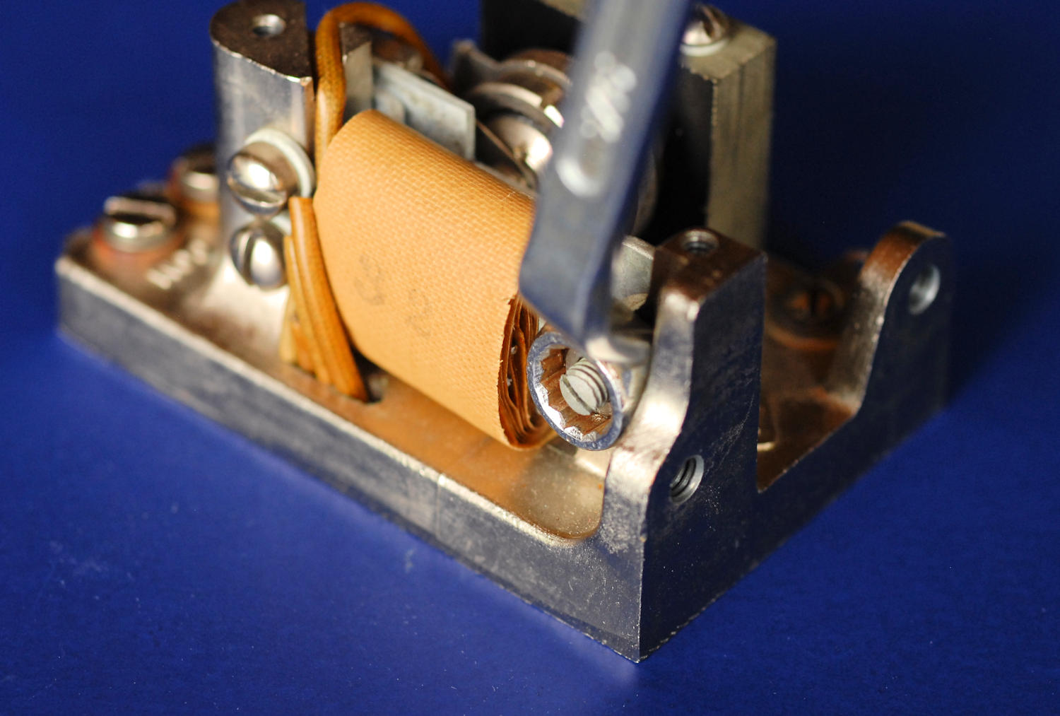
The magnetic gap is adjusted with the setscrew and locknut on the back of the unit. It's impossible to access without an offset 5/16" box end wrench to loosen and tighten the nut. You'll probably have to remove one screw from the big capacitor on top (if present) and twist it sideways a bit. GR says if you close the gap too much, the output will have more harmonics, but it will start more easily. Keep the gap as large as possible. If you have a THD meter you might be able to optimize it. Or not, as the output is highly dependent on the orientation and the condition and tension on the rubber support bushings, the phase of the moon plus a few other things I'll mention.
In most applications (the 650-A bridge for example) there will be a 0.5 uF 300 volt capacitor mounted on top of the hummer, usually an Aerovox. This cap smooths the waveform and reduces harmonics. It contains two wax paper roll capacitors and can go bad- high DC leakage and rising value. You can heat it up with a hot air gun, remove the base and tar, then rip out the side spacers and caps. The leads will tear out, then you can unsolder them from the top terminals. Install new film caps. I used a couple 1 uF 200 volt polyester caps in series. That gave me the original value and rating, though I see no reason the unit needs anywhere that voltage rating. A single 0.47 uF 50 or 100 volt cap should be far more than adequate. The capacitor is wired between COM and HI.
If you must service the mic capsule, carbon granules might be had from an old telephone mic cartridge. Apparently the granules are crushed and treated anthracite coal! I've measured the particle size at about 0.010" to 0.014". It was very consistent, no fines or lumps mixed in. I don't know if it's something that can be created DIY, but it's worth a try. Start with some hard anthracite from your local coal dealer, a hammer and some fine screens. Maybe settle it out in water to eliminate the finer dust. Older telephone patents might give some clues. There are still carbon mic cartridges on eBay. Note that the one I took apart used surprisingly little powder, so you may need a couple to rebuild the microphone capsule.
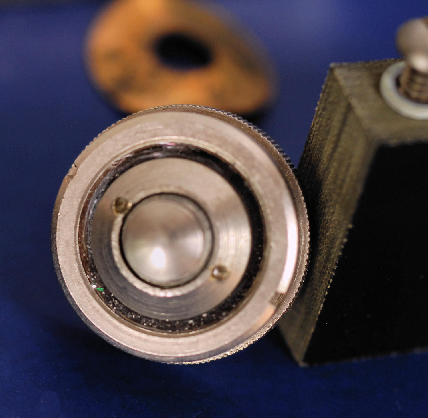
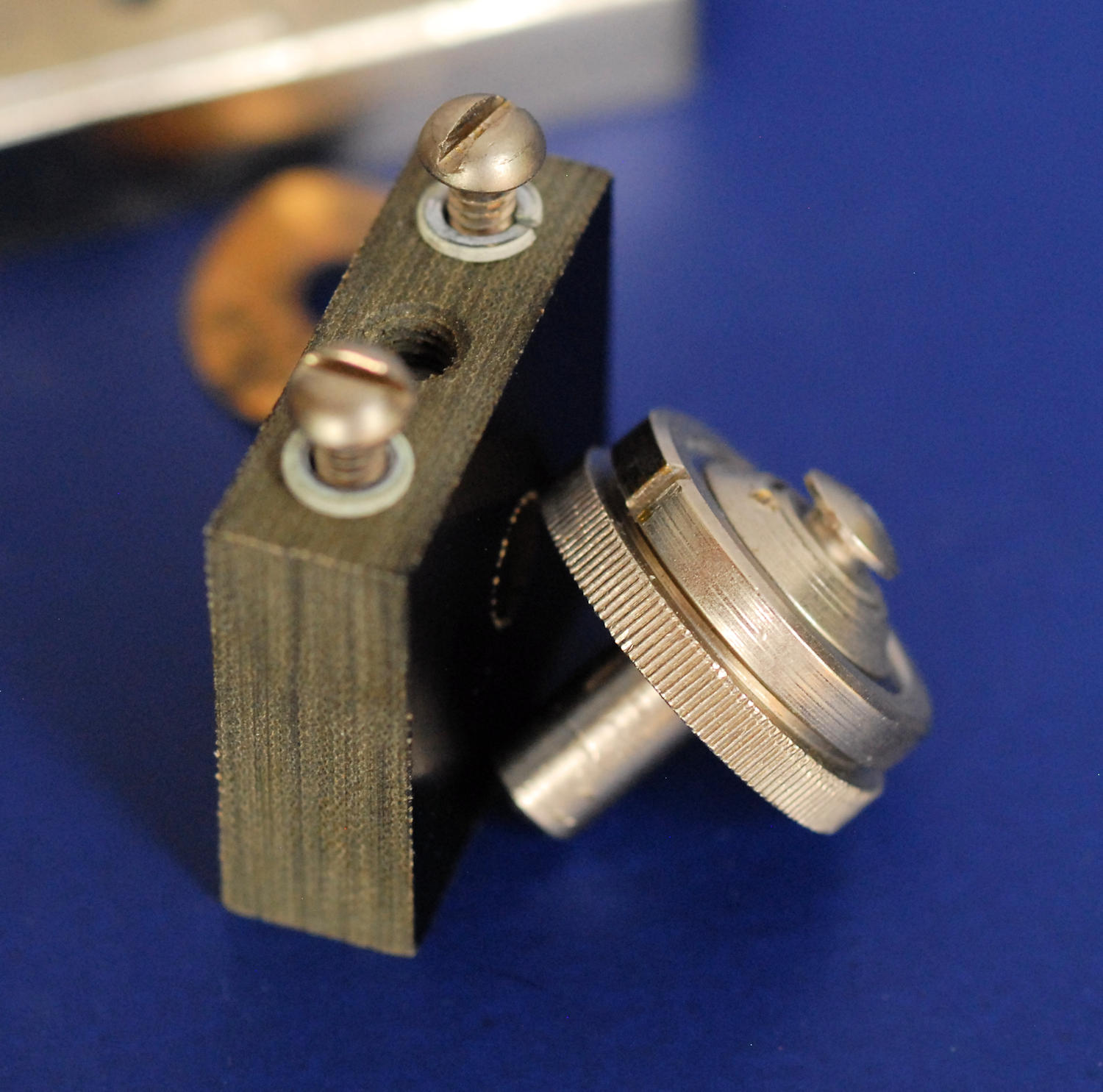
The diaphragm is a mica disk with a hole in the middle, about 0.002" to 0.003" thick. It's quite difficult to get the parts screwed together so everything is centered, and you might need to make a suitable pin spanner. The internal faces seem to be a hard black carbon button. I suspect the mic shouldn't be tightly packed but should have some space for the powder to move around. Keep everything clean and free of fingerprints. I'd love to hear from anybody that's had success rebuilding these. Here's a shot of the microphone capsule where you can see the carbon granules through the mica at the bottom, and then a side view.
The overall adjustment process is very much trial and error, plus a bit of luck. First, understand that the carbon microphone isn't a very stable device. In the old days you had to whack the telephone every now and then to clean up the sound. The 572-B will change amplitude and sometimes be fussy about starting at all. Tapping the microphone area with the handle of a small screwdriver will tend to stabilize it. I'm not sure what the official output should be, but with no stabilizing cap, 3-5 Vrms seems typical for a 6 VDC drive.
You have several things to optimize, all interrelated. It's important to loosen the microphone capsule during major adjustments because you don't want to damage the mica diaphragm. Here's a list of things that matter.
During all of this, keep tapping the device with the plastic handle of a small screwdriver. Try the hummer in various positions, especially the one in which it will be used. If you see excessive power consumption at any time, more than a few tens of mA, stop and tap the microphone cartridge. Check that the tip hasn't been pushed in, crushing the carbon granules together. Typical resistance of the microphone capsule seems to be about 200 ohms, with excursions between 25 and 400 if you excite the tip. With luck, your hummer will be fairly stable, producing the same waveform each time you power it up. Remember though, it's a somewhat crude thing compared to a modern solid state oscillator and some variation is normal and expected.
C. Hoffman
last major edit July 15, 2018