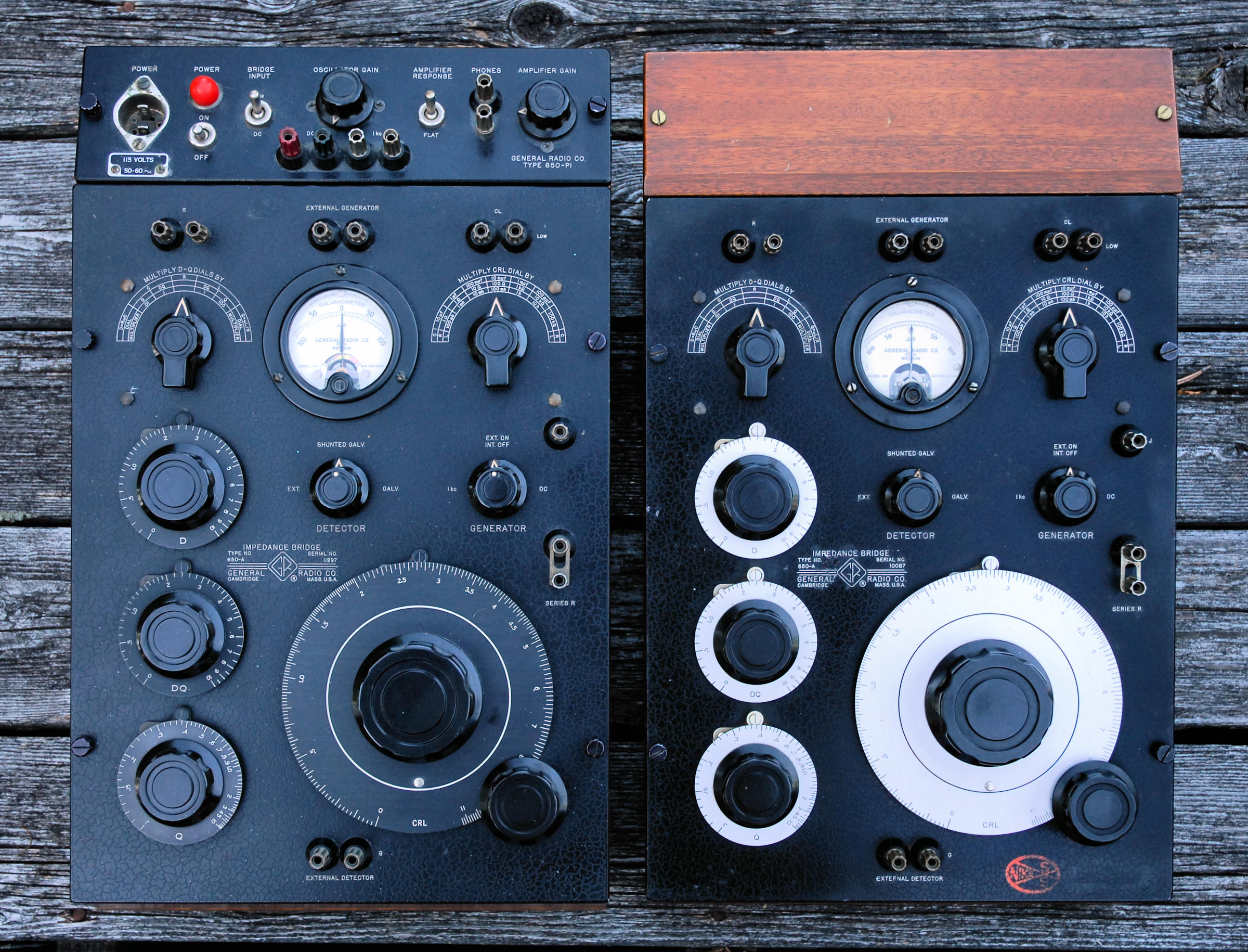

The GR 650-A was a general purpose CRL (capacitance, resistance and inductance) bridge. It was designed by R.F. Field, who joined General Radio Corp. in 1929, and introduced it in the April-May 1933 issue of The General Radio Experimenter. Think of it as the DVM of component measurements of its time. It's battery operated and has a handle, making it "portable", though at 22 lbs without batteries you won't want to go very far with it. It cost $175 in 1936.
On the right we have a GR 650-A with light dials and a low serial number. The one on the left has dark dials and a much higher serial number, with the optional 650-P1 oscillator/amplifier installed. The 650-P1 was received installed in the light dial unit, but I swapped it into the other. Being sold as an accessory for any unit, the swap didn't seem like too much of a violation of history. I'm not sure when these were produced, as both earlier and later catalogs seem to show the same photo of a light dial unit, possibly a prototype, with no GR logo in the text on the front panel. I have no catalog showing dark dials. By the "P" catalog the 650-A passed into history, replaced by the smaller, lighter and more capable 1650. As far as I know, there were almost no changes in the 650-A from the beginning of production, to the end.
The basic unit is battery operated and contains a microphone hummer that generates a usable, though not terribly pure, 1 kHz sine wave. The AC signal was detected using the very sensitive high impedance headphones of the time. High impedance headphones are no longer made and modern 'phones don't give nearly as good a result. The batteries also provide DC voltage directly for resistance measurements. DC balance is observed on the built in panel meter.
The 650-P1 is AC powered and generates an improved 1 kHz signal, plus a much higher DC voltage for resistor measurements. The DC voltage is limited by resistors so it varies depending on what bridge range is in use. It can be as high as 180 VDC, so some caution is needed not to touch terminals when the DC supply is in use. The manual touches on this, but doesn't come right out and specify the voltage, though the catalog page does. They probably figured you'd quickly learn not to touch the terminals entirely on your own! You can reduce the voltage if necessary by adding some parallel resistance across the terminals. It also has an adjustable AC amplifier and, though still intended to drive headphones, provides vastly more gain so a better null can be achieved. There is a selectable 1 kHz filter to reject hum and other interference, further improving the ability to null the bridge. In fact, with the 650-P1 in place, sensitivity can be so high that each wire of the main CRL dial is easily, even excessively, discerned.
The 650-A covers capacitance from 1 pF to 100 uF, resistance from 1 milliohm to 1 megohm and inductance from 1 microhenry to 100 henries. Accuracy is generally better than 2%, save for dissipation factor and inductance measurements. Bridges can be pretty fussy about the generator and detector hookups, and unwanted capacitance associated with them. The 650-A does not contain its own bridge transformer, so care must be used if you supply your own signal source. The battery operated microphone hummer and battery-based DC supplies are, of course, fully floating. The 650-P1 contains it's own low capacitance signal isolation transformer.
The 650-A is sufficiently accurate for most purposes, but doesn't really shine with low dissipation factor measurements, as the published specifications show. The internal 505 standards are good, but internal strays (or something) prevent it from taking full advantage of them. It will read about half the dissipation factor on a Mylar cap, then the cap is known to have. The value, however, will be dead on. It does just fine with electrolytics, which always have higher dissipation factors.
It's interesting that in 1951 Heathkit sold a near carbon copy of the 650-A as their IB-1B. It even used the same microphone hummer, but less expensive switches and construction. It still cost more than most hobbyists could afford.
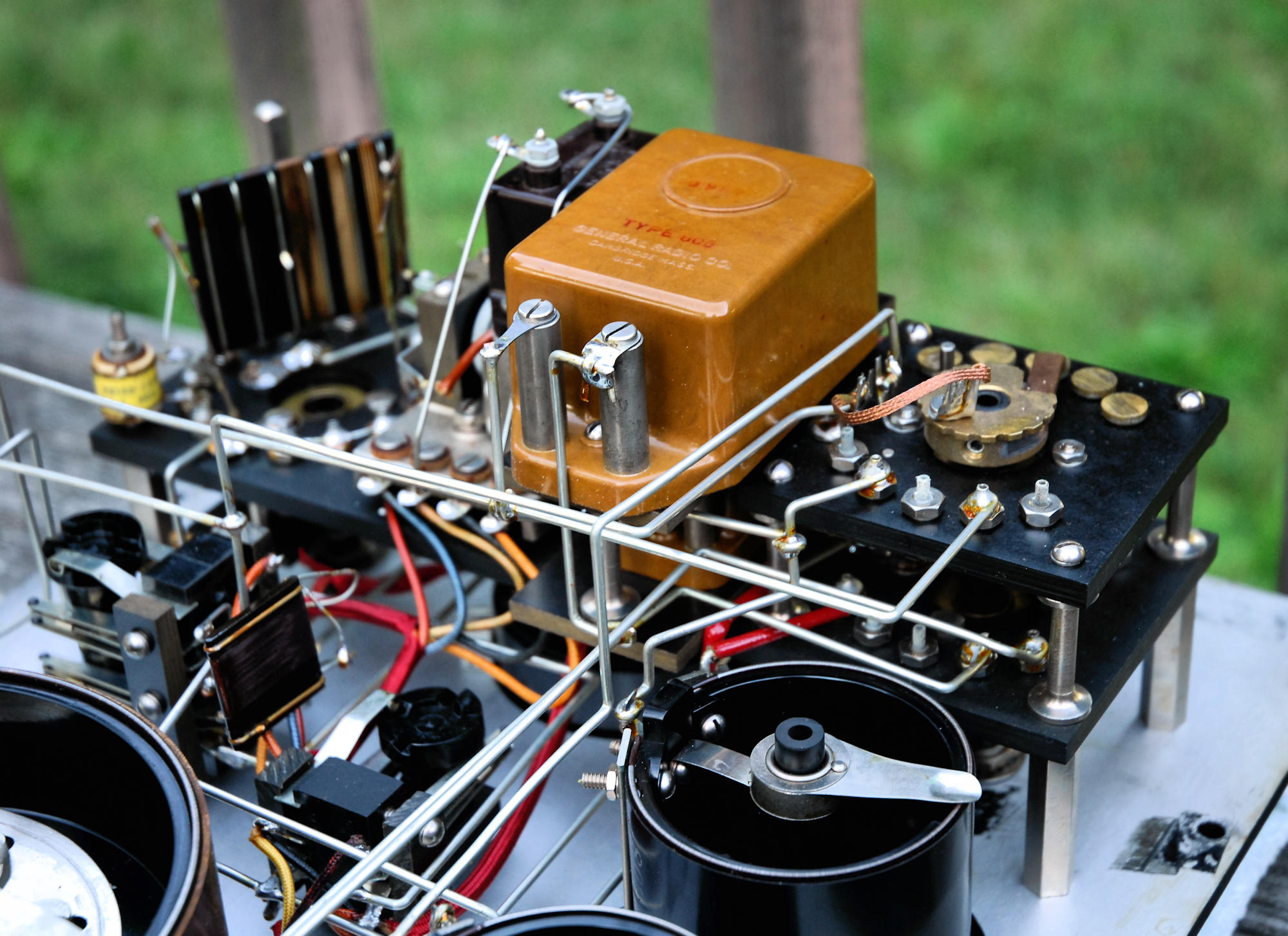
The 650-A is built like a tank, as is everything General Radio did. They usually don't require much service, save for cleaning of the pots and switches, unless the windings are damaged. The microphone hummers are a bit finicky, and the big Aerovox capacitor on top of the hummer might need to be replaced, or restuffed if you want to maintain the original internal appearance. I was going to put some hummer notes here but decided it needed an entire page to itself.
One of the manuals circulating on the 'net has a peculiar hand written note concerning the 650-P1. It says if the two panels touch, the panel meter will be shunted and give low sensitivity. If the 650-P1 is properly installed, the grounded shield of the detector cable is solidly tied to the ground of the 650-A, so there should be no problem if whether the panels touch or not. Once again, if anybody knows differently, please send me a note.
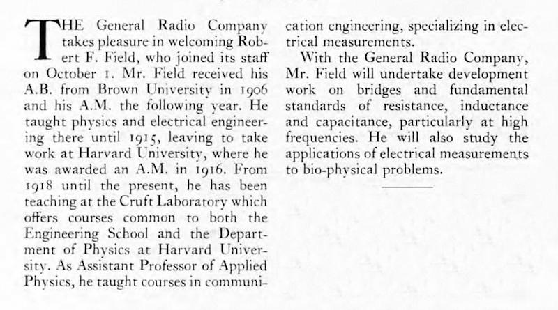
Here's the hiring announcement for R.F. Field from the October 1929 issue of The General Radio Experimenter. I'm convinced that his fate was sealed from the moment his parents named him:
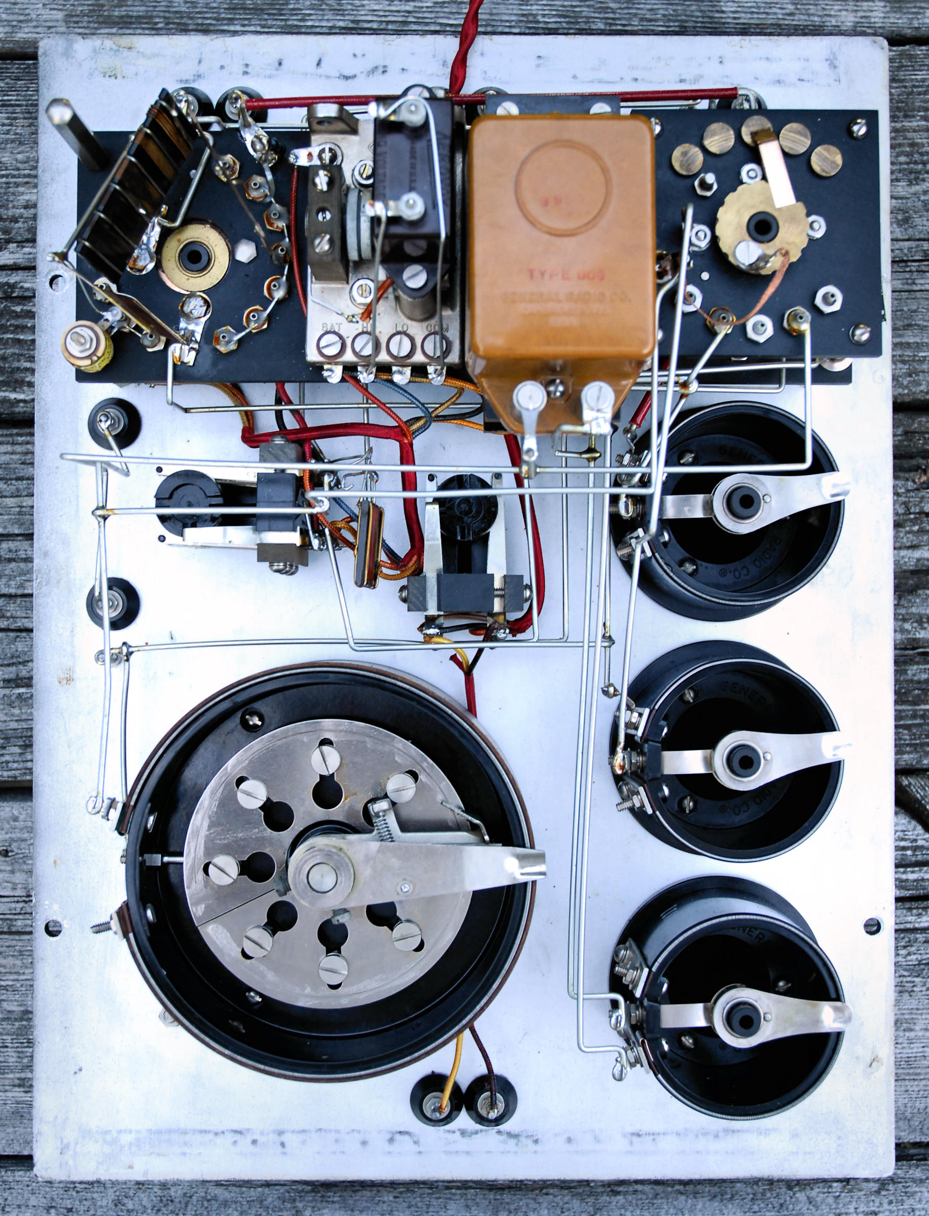
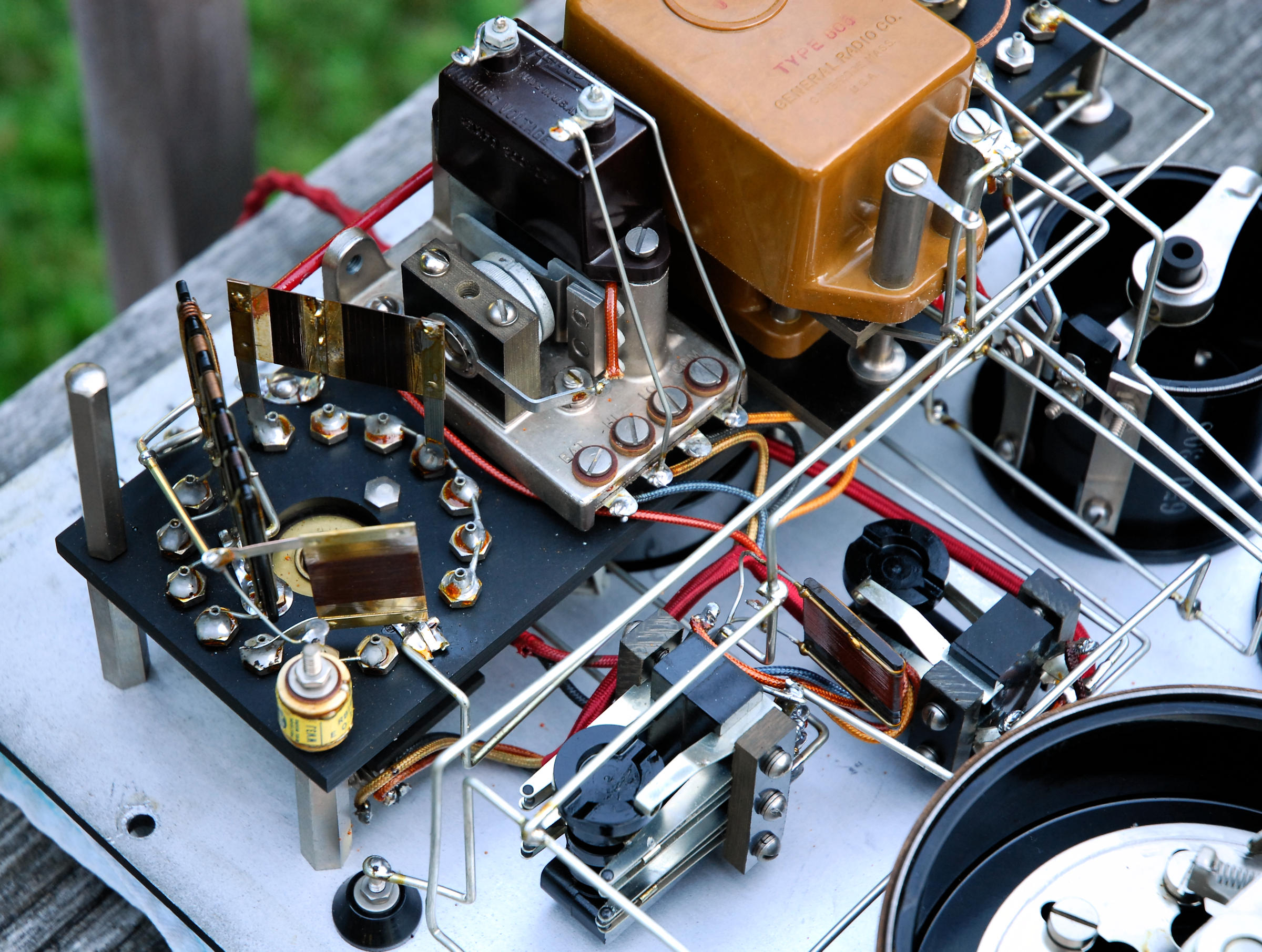
Below are some photos of the internal layout of the bridge. First the overall layout, then a better view of the microphone hummer and finally the reference capacitors. You can just make out the smaller one (0.01 uF) that lives underneath the larger one (0.1 uF). The capacitors are the GR 505 mica types.
A nice 650-A is essential to a complete GR bridge collection, and it would certainly do a decent job with low value resistors, capacitors and inductors if you wanted a "user". That said, it's large in terms of bench space, and there are much better choices. The 1650 A or B is smaller and more accurate or, if you need low DF measurements, the 716-C is the bridge to have. One place where the old mechanical bridges can't be beat is for measurements under bias, especially high voltage bias.
C. Hoffman
last major edit July 15, 2018