The GR 716-C Capacitance Bridge
I consider the 716-C to be one of the high points of GR bridge design. Introduced prior to 1942 as the "A" version,
it was still listed in my 1970 "U" catalog, so it had a run of at least 28 years and maybe a bit longer. They come in
all paint schemes from early engraved black, to engraved dark gray, to silk-screened light gray. Cases range from none, to
standard metal, to a very nice wood.
The 716-C is a Schering bridge covering a range of 100 pF to 1.1 μF at 1 kHz in direct reading mode. In substitution mode, values
down to about 0.2 pF can be read. Accuracy is .1% if the dissipation factor is low. A big feature of the 716-C is the ability to read
D down to .00002; in fact its ability to read dissipation factor was given just as much design attention as getting an accurate
capacitance value. This was the feature that first caught my interest for audio work.
A frequency range of 30 Hz to 300 kHz is claimed, and substitution measurements can be made at reduced accuracy to 1 MHz. There's
also a 716-CS1 variant that's good to 1 MHz, with reduced accuracy to 5 MHz. Note that the CS1 doesn't have a range selector switch,
so it's far less versatile than the standard model. Some dealers get a premium for the CS1, but I consider it less desirable than
the C unless one has a specific need for higher frequencies over a narrower measurement range.
My 1956 manual is silent on the matter of applying DC bias to the instrument, but a later 1968 manual describes the usual T-fitting
to the DETECTOR terminal to apply DC bias. A variable DC supply is limited and (for 1 kHz measurments)
filtered by a CRCR filter using two pairs of 0.005 µF caps to ground and two 10 MΩ resistors in series. The detector is
AC coupled (1232 normally is anyway) with a 0.005 µF capacitor. The later manual is also more desirable because it has an
improved schematic that shows the range connections more clearly, and has a much more detailed calibration procedure. If you can get
a later manual, use their procedures, not mine! Note that you can also apply higher AC voltages to the DUT by reversing the
GENERATOR and DETECTOR connections. (Bridge panel markings will be indicated
in white throughout this write-up.)
The manual covers other applications like measuring very high resistance values of up to 80 kMΩ (today we use GΩ), and
large inductors from 25 H to 1 MH (1,000,000 H). No, I've never seen a 1 MH inductor either- let me know if you run across one!
Operation of the bridge is straight forward for anyone used to balancing a bridge and there's little more I can contribute there.
Remember to multiply the reading on the dissipation dial by .01, and by the frequency ratio, to be in agreement with the numbers given
here. The biggest problem I had with my 716-C was calibration. The manual is rather cryptic on the matter, so I've added some
notes to smooth the process. You should still have the manual for the schematic, general process, and locations of the trimmers,
though they are usually labeled on the shields. The manual can be downloaded from several sites for free. The older 716-A bridges
don't have high and low frequency ranges, nor a substitution mode, so calibration is just an abbreviated version of the 716-C
procedure.
Calibration Notes:
- The 716-C will balance for capacitance over a wide frequency range but the dissipation balance is frequency sensitive and
almost all of the calibration involves the dissipation factor circuitry. For best results monitor your oscillator frequencies
with a counter and keep them as close to the nominal values as possible.
- Collect measured standards of 100 pF, 1000 pF, .01 μF, .1 μF, and 1 μF. You will need to know the dissipation factor
of each, though most silver micas will be about .0005. A Digibridge measurement is sufficient for capacitance, but you really
need to do better on dissipation factor (unless you have one of the better Digibridges) so the low end of the 716C is accurate.
If you can't get access to a 1615 or similar, get the 716C close, then do a substitution measurement to get a good dissipation
factor reading for the two lowest standards.
- Calculate an additional standard having a dissipation factor of .05 near 1000 pF. Mine was a 1085 pF silver mica in series
with a 10 kΩ trimpot set to 7330 ohms. Remember that this dissipation standard is only valid at 1 kHz. You would have to
change the resistance value for other frequencies, if desired. R=D/(2*Π*F*C), not including the dissipation factor of the cap,
which should be much lower. There are error terms that must be accounted for as dissipation
factor increases, so use this standard only for dissipation factor, not capacitance.
- Now would be a good time to clean and lubricate the big RANGE SELECTOR switch. Use a Q-tip to
clean the posts and apply a thin film of petroleum jelly.
- Balance the bridge in DIRECT mode using the dissipation standard on the
1kc 1 scale. The DISSIPATION FACTOR dial should read 5 (5x.01=.05). Remount the dial
on the capacitor shaft to correct if necessary. It will usually be necessary to open the shielded box and hold the plate assembly
to get this right. There are two places where it can balance, only one of which is correct. As the dial is moved off zero to a
higher value, the straight back edge of the plates should not start to engage; the curved engaged part should engage
further. That is, higher dissipation factor requires higher capacitance. Be sure the vernier knob correctly engages the metal
disk on the back of the dial. The metal disk should be gripped between the two flanges. Note that GR vernier knob bushings are
eccentric. They can be adjusted for engagement by loosening the mounting nut on the back of the panel, then rotating the bushing.
On the 716-C the enclosure has to be removed from the front panel to access the nut so hopefully it was adjusted correctly to
begin with. Be sure the main dial has correct clearance to the panel so as not to scratch, and the index mark rides smoothly on
top. There is some interaction with the high and low calibrations of the DISSIPATION FACTOR dial.
Expect to perform the calibration twice if the bridge has been rebuilt or is seriously out of calibration.
- All trimmer adjustments are for dissipation factor only. They have a tapered locknut that you should loosen with a nut
driver before adjusting them. The DIRECT trimmer is the master for all the others and should generally
be left alone. It's used to tweak the bridge for temperature changes, so setting it with the plates half engaged would be a good
starting point. Balance the bridge at 1kc 1 with the 1000 pF standard and adjust the
1kc trimmer so perfect balance occurs at the known dissipation factor minus 0.00004, the dissipation factor of the main
capacitor when set near 1000 pF. In other words, subtract 0.00004 from the dissipation factor of your calibration capacitor and
set the dial to that number. Adjust the trimmer for the best balance at that setting. There will be some interaction with the
proximity of your body so it may help to rest the outside cover about halfway on to provide some extra shielding.
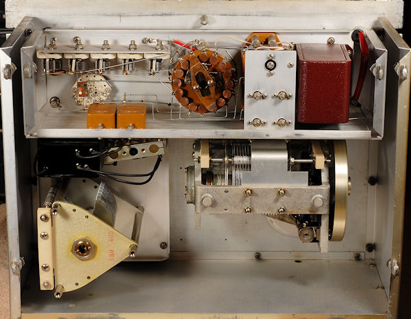
There isn't all that much inside a 716-C. Here's the view from the back with the covers and dissipation capacitor box removed.
- Flip to SUBST and adjust the SUBST trimmer so the bridge balances on the
other side of zero by the same amount. I.e., the bridge should balance at symmetric points around zero for
DIRECT and SUBST. Don't accidentally adjust the DIRECT trimmer by
mistake like I sometimes do. Go back to DIRECT mode.
- Balance the bridge at
1kc 10 with the .01 μF standard and adjust the X10 trimmer.
- Balance the bridge at
1kc 100 with the .1 μF standard and adjust the X100 trimmer.
- Balance the bridge at
1kc 1000 with the 1 μF standard and adjust the X1000 trimmer.
- Balance the bridge with the 1000 pF standard at the other frequencies and adjust the associated trimmers. I'll talk more about
the 100 kHz adjustments shortly.
- The capacitance calibration can be touched up by adjustment of the sheet metal piece on the main capacitor. It can be moved up
and down for large adjustments, or just warped in and out slightly with the upper screws for fine tuning. Again, the metal cover
will affect the final value substantially. (Do this at 101 pF, see manual section 6.21) Getting an older 716-C perfect can take
some fussing. Oily capacitor plates will have too high a value, so don't spray it with anything containing a lubricant! On very
old units the metal box that shields the dissipation factor capacitor can short out to the metal section above, resulting in a
non-working bridge (or I had one with some unusual problem that caused this). A small piece of perfboard between the two will
prevent this. Later bridges have the parts solidly wired together and it's normal for for the screw heads on top to touch the
bottom. The exact construction may be vintage dependent, though it's somewhat remarkable how little changed over the many years
they were built. Watch out for shorts between the free-floating buss wires and various chassis parts and mounting screws. Check
the tightness of all screws, and the nuts on the back of the banana terminals. Check all solder joints, particularly the jumper
to the center plates on the C20 balance capacitor. GR rarely messes up, but I have seen this one go unsoldered because it can be
hidden under the wires.
If necessary, the main capacitor can be removed by unsoldering a single wire with a long thin soldering iron. Remove the knob
and three large bolts, and it will come right out. Clean the ceramic insulators with solvent and blow the dust out with
compressed air. If you use denatured alcohol it will leave moisture on drying and the parts will need some time before the
leakage resistance goes back up to where it should be. Don't leave fingerprints. The grease in the spherical bearing and on the
worm gear may be dried out, so clean and relube as necessary. The dial needs to move very smoothly, with no "stick-slip",
if you expect to achieve very precise balances. There are three calibration "adjustments". First, you can warp the sheet metal
plate using the two adjustment screws on the back. This will, I believe, shift the low end of the range by a few pFs, or maybe the
whole scale. You can also shift the position of the two dials; be sure the readings on the large drum line up exactly when the
front dial reads zero. Example- using another capacitance meter, set the capacitor to exactly 1000 pF. Loosen the front dial and
set it to exactly zero. Loosen the drum and set it to exactly 1000 pF. Reinstall the capacitor in the 716-C. You'll likely be
within a few pF. Test the calibration with a known standard. If it's close, adjust the sheet metal plate. If more adjustment is
needed, remove the capacitor and change the front dial by the amount needed. Realign the drum. Reinstall. Don't forget to resolder
the wire! Finally, if the linearity of the capacitor is off, the split plate can be bent to compensate. This is beyond most peoples
abilities and equipment, but if you have another known good capacitance meter, you can do it. A 1615 is probably best, but a
Digibridge is sufficient and far more convenient.
Remember that the 1.1 pF capacitance between the UNKNOWN DIRECT terminals is not compensated, so all
readings should be 1.1 pF high.
100 kHz & The Mysteries of Adjusting C20
C20 is used to compensate for internal leakage so that the dissipation factor reading is correct at both ends of the main
capacitor. At lower frequencies you calibrate at 1000 pF and the reading at 100 pF will be very close. At 100 kHz and higher this
is not the case and C20 is used to compensate. I had a difficult time with this adjustment until realizing that even the slightest
signal pickup at any terminal will make the adjustment impossible. First, both the GENERATOR and
DETECTOR terminals have to be fully shielded. To that end, GR made locking shielded banana-to-BNC adapters
like these.
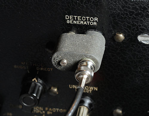
They also made something similar for the GR-874 hermaphrodite connectors, if you prefer those.
Next, the adjustment can only be made with an outer cover in place. Since we don't want to drill holes in the factory cover, the
easiest thing is to cut up some common aluminum roofing flashing and put holes in that. I only had pieces of flashing that were
too narrow and in two different colors, but the two overlapping pieces worked just fine.
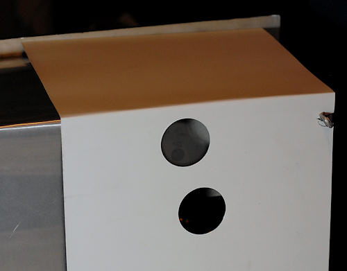
With shielding in place the procedure is still tedious, but the odds of success are far greater. With the bridge set to
100kc 1 balance your 1000 pF standard and adjust the 100 kHz trimmer for
the correct dissipation factor. Switch to your 100 pF standard and crank the main capacitor down to balance. Adjust C20
(TRANS) for the correct dissipation factor. Remember that at the lower
end of the range you subtract 0.0004 from the standards actual dissipation factor, as that's the dissipation factor of the main
capacitor at the lower end. The upper end is 0.00004, but remember these are factory estimates, not absolute truth for every
bridge. By going back and forth between the 1000 pF and 100 pF standards you should be able to get the lower end very close to
the correct dissipation value. My experience is that some bridges can be adjusted much closer than others and it may be related
to the leakage problem described next.
Leaky Insulators
Leakage between the internal shields and ground is a common problem on older 716 bridges. Based on tests of quite a few units, it
may be a universal problem as a good one has yet to be found. You can check for this by measuring the resistance between the
UNKNOWN SUBST terminals on the front panel, or between the DETECTOR terminals. A
low reading usually indicates that the large phenolic insulators supporting the shields and their circuitry have become leaky. I've
seen a reading as low as 15 MΩ on an older unit, though my friend Eric appears to hold the world record with a leakage
resistance of 1.5 MΩ. Cleaning the insulators only made it worse. Baking didn't help. The best theory at the moment is that
the brass inserts and aluminum chassis surfaces have produced salts or oxides that permeated the porous phenolic and formed a
conductive path between the two inserts.
Fabricating new parts is the best solution, though another method exists for those without the capability to do this. More on that
in a bit. The big question you're probably asking is, "How bad does it have to get before I fix it, and what are the symptoms?"
I mentioned above that I had a bridge with 15 MΩ leakage, incredibly bad in my opinion. When trying to calibrate it, the big
problem areas were the 100c 1 range and, to a lesser extent, the bottom end of the
1kc 1 range range. At 100 Hz, the dissipation factor went wildly high as the capacitance values decreased. That range was
essentially unusable. On the 1kc 1 range things weren't as bad as I expected. The dissipation factor at
100 pF was only slightly high, about 0.001 or a bit more. I was unable to calibrate the low end of the 100kc 1
range using C20. On the upside, the 1kc 10, 1kc 100 and
1kc 1000 ranges didn't appear affected at all.
So, if you don't make unusual demands on the bridge, tend towards values closer to 1000 pF, or values that use the upper ranges,
you might find you can live with remarkably high leakage. Personally, as a certified GR nutcase, I'd be concerned if the resistance
were under 100 MΩ, and from the main capacitor specifications (d=.00004 at 1000 pF and d=.0004 at 100 pF) one would expect it to
exceed 4 GΩ. That's a far cry from 15 MΩ!
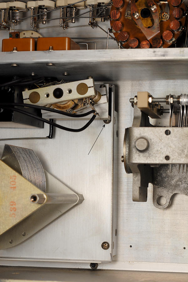
This is what one of the original insulators looks like.
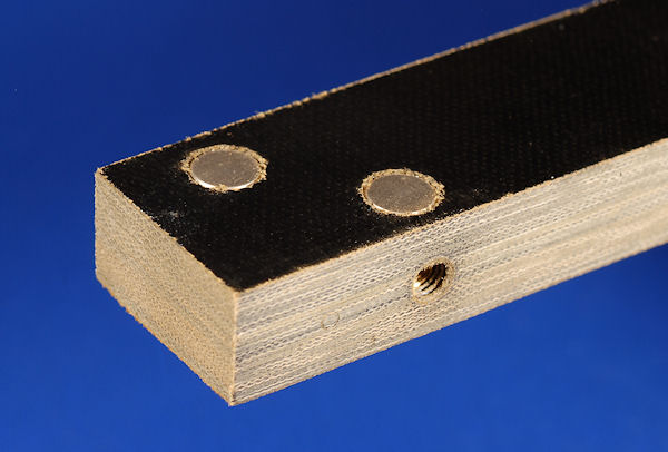
The screw indicated by the arrow can't be removed without major and probably destructive disassembly. Don't even think about
it! The screw has to be turned with a small flat bladed screwdriver a fraction of a turn at a time. You can just see a bit of the
new insulator that's been installed.
I've made suitable replacements from thick Lexan. You can tap it directly, rather than use brass inserts like the originals. I've
also made copies of the original insulators using polypropylene and transferred the inserts from old to new. Polypropylene is
probably the ultimate insulator material and it should be available in 1/2" thick sheets. Teflon will work but is rather soft.
Click here for a PDF format drawing of the insulators. Make no mistake, this is a fairly
difficult repair and not for the faint of heart. Not only do you have to make the parts accurately, you will have to remove the
outer sheet metal housing from the front panel, twist the generator transformer a bit, and coax an inaccessible and nonremovable
screw inside the DF cap box, a fraction of a turn at a time, to replace the parts. All four insulators have to be replaced; it does
little good to do any less. There is some risk of damage to various components that could potentially turn the bridge into a parts
donor, so be careful and patient if you decide to do this.
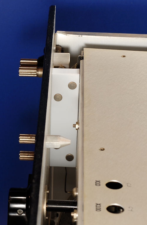
Here's a newly installed polypropylene insulator using the original brass inserts pressed out of the old parts. This bridge
went from 150 megohms to 30 gigohms when the new insulators were installed.
If you don't have the tools to fabricate new insulators there is still hope. My friend Eric came up with a fairly effective fix,
though it may not give quite as high a resistance reading as out and out replacement. The bronze bushings are pressed out of the
insulators and put aside. Using a size larger drill bit, enlarge the holes to 21/64". Wash everything with hot water and let dry. A
mild baking is advisable to get every trace of moisture out. Thin some Q-dope (or something similar) and coat the inside of the
holes. Allow to dry. Coat the bushings and press them back into place. Install some #10-32 screws to be sure the tapped holes line
up and are square. Allow everything to dry with the screws in place. Check the resistance between the screws then reassemble and
enjoy.
I've had at least one 716-C that just wouldn't calibrate. Possibly the normal stray or residual capacitance changed over the
years, or, more likely, there was some other failure mode I couldn't locate. As a last resort, C10 can be adjusted. C10
is the vertically mounted 33 or 35 pF capacitor tacked between the buss wires near the SUBST and
DIRECT trimmers. The "A" arm is schematically on the left, and contains the internal standard
capacitor. The "B" arm is on the right and contains the unknown. In DIRECT mode X1, all DF caps and
trimmers are across the top of the "A" arm. This capacitance is compensated on the "B" arm only by C10 and strays. Thus, altering
C10 can compensate for a variety of hard to identify changes in the bridge. This should only be done after all efforts to
locate the fundamental reason for the change have been exhausted. Save the original C10 as sooner or later the real problem might
reveal itself.
Now, check it all again until your 716-C is as accurate as GR designed it to be!
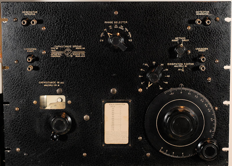
My daily user has some smudges and a bit of wear and tear, but it's deadly accurate and I prefer the look of the earlier black units
over the later dark and light grey versions.
Leakage Measurements
One of the most convenient tools for measuring leakage, both in the bridge and in the capacitors we're testing, is the HP 4329A
High Resistance Meter. Unfortunately they aren't that common and, in spite of their age, tend to be expensive. There are other tools
like the "Megger" for insulation resistance measurements, but as I haven't used them I can't comment on their suitability. You can
measure leakage with a moderate voltage power supply, a couple resistors and a good DVM. Equip a 100 VDC power supply with a
protective current limiting resistor of about 100 kΩ. Connect that to the DUT, say the isolated UNKNOWN
SUBST terminal. Connect the DUT (the chassis in our case) back to the power supply ground through your DVM, set to VDC.
Because we want to measure a very small current, it's better to use the VDC scale rather than the current scale, as the shunt
resistance will be 1 or 10 MΩ, rather than some fractional ohm value. With a 10 meg meter like a Fluke handheld, you should see
less than 250 mV if the leakage is over 4 GΩ. (warning- I haven't tried this method!)
Noise Pickup
I sometimes want to look at the bridge residual with an unfiltered detector like a preamplified scope. To keep noise pickup to a
minimum, extra shielding is required. All the active terminals of the bridge are potential inputs. I use fully shielded banana plug
adapters (GR banana-to-BNC types) for all connections. I also place one over the UNKNOWN SUBST terminals,
though that alters the calibration slightly. Finally, the metal shaft of the METHOD switch is a troublesome
antenna, so a grounded metal chassis/box can be supported to cover both the DUT and the METHOD knob/shaft.
C. Hoffman
last edit August 28, 2010
HOME


