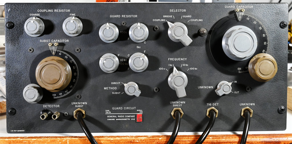

Described in the August 1952 Experimenter, the GR 716-P4 is an external guard circuit used with the 716-C capacitance bridge to give it 3-terminal measurement capability. This allows making shielded measurements at a distance, without the cables contributing to the measured value. It only works on the X1 range of the bridge, so 150-1100 pF. That's not much of a limitation because at higher values of capacitance you don't really need 3-terminal measurements. The circuit is also known as a Wagner ground. The guard circuit isn't something most 716-C users needed and I suspect an order of magnitude more bridges were made then guard circuits, thus their infrequent appearance on the used market. The bare rack mount version is 716-P4R. It was also available in a wooden cabinet as 716-P4M to match similarly cased bridges.
The units are surprisingly simple, containing three variable capacitors and a few ordinary Allen-Bradley pots. The trick is in the shielding. Having about given up on ever seeing a real one, I considered building the circuit from scratch. Without really understanding the shielding it would have been an exercise in frustration. By luck, two appeared simultaneously on eBay and I purchased what appeared to be the better example. I've never seen photos of the internal construction so I'll try to take some good clear photos for this page.
You'll notice that two of the knobs have turned brown. That happens to some GR knobs for unknown reasons. It isn't exposure to something since no other knobs are affected so there must have been some difference during manufacture. If I ever learn of a way to get the grey color back I'll certainly describe it.
If you look at the front panel you'll see a metal knob-like thing between the selector switch and the guard capacitor dial. I didn't have a clue what that was until I opened the back. It's a hole plug with a handle so you can adjust the small trimming capacitor shown below. It's mentioned in the fine print on page 4 of the manual, but there's no procedure to adjust it.
Here's the inside of the unit with both the rear cover and internal shield cover removed. You can see the internal shielded box is supported by two phenolic blocks, just like the construction of the GR 716-C bridge. Overall it's remarkably simple, solid, and should be trouble-free.
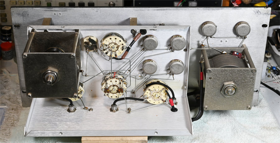
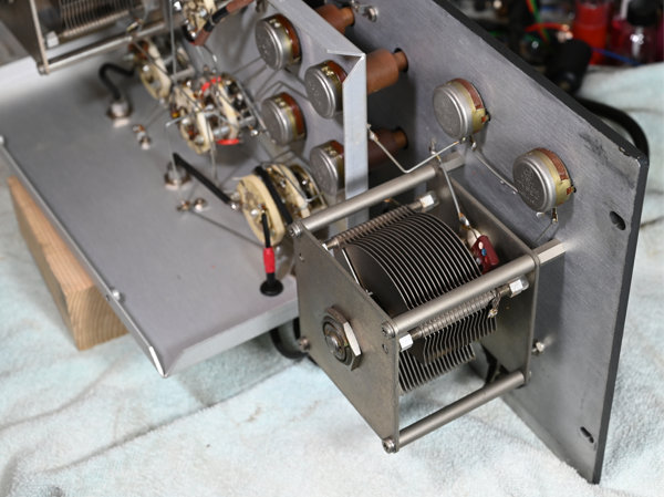
Here's a closer shot of the guard capacitor.
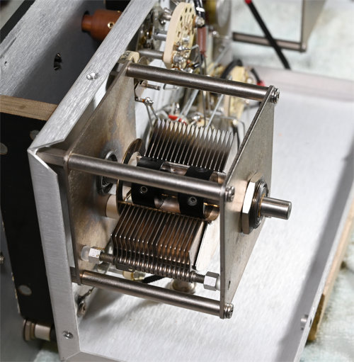
To keep the insulation resistance high and the dissipation factor low on the guard capacitor, they supported the fixed plates between glass, possibly quartz, balls. Pretty clever engineering.
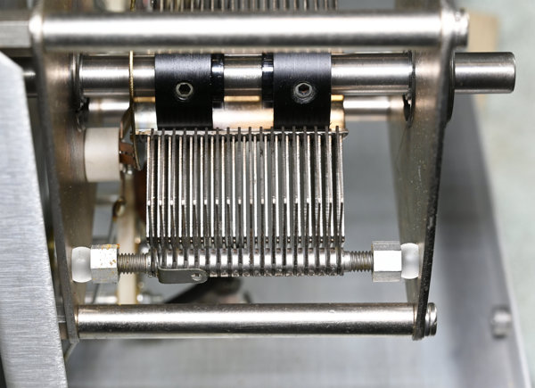
The substitution capacitor is the same type as the guard capacitor, though it doesn't live inside the internal shield, only the outer aluminum cover. Having a built-in substitution capacitor is a really nice feature. When doing substitution measurements with the 716-C you always needed to locate a suitable decent quality and appropriate value part, and attach it.
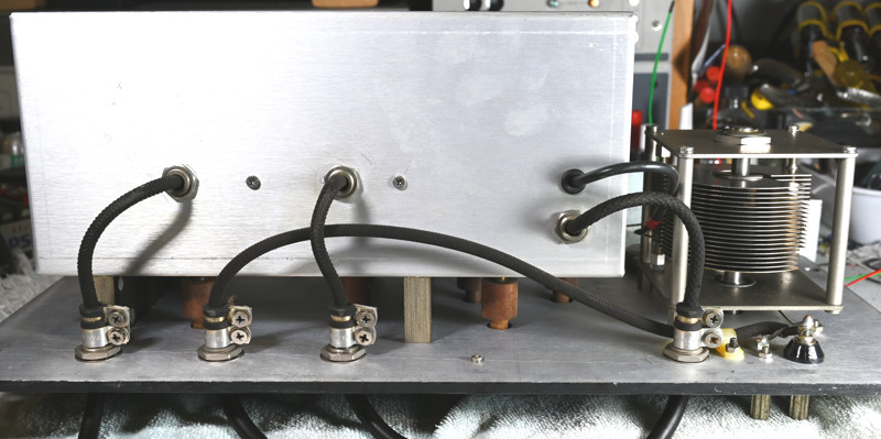
Naturally GR machined or had made fancy custom cable clamps for where the cables enter the instrument. The "unknown" and "716 detector" cables are triaxial.
The GR crackle finish is fairly durable, but will be damaged by almost all solvents. Even ammonia cleaners are bad news. I use original Armor All on GR panels, immediately followed by polishing with a soft cloth. For stubborn tape residues a little WD-40 is OK, or a long soak under a wet paper towel. Beyond that it's best to learn to live with markings and such, as the GR finish is difficult (read impossible) to duplicate. GR and others used that crackle finish in various colors over many decades yet no one today seems to remember how to do it. Even if you could duplicate it, the lettering was engraved through the paint, something beyond most of our home shop capabilities.
Those blocks supporting the internal shielded enclosure are known to become conductive over time and usually have to be replaced, at least on the 716-C. I've got more detailed notes on that in the 716-C write-up. A resistance measurement from the chassis to the internal box gave 120 megohms at 25 volts. That's pretty good and might be the phenolic blocks or possibly the shielded cables. Or both. For the moment I'm going to leave well enough alone, but loosening the screws and remeasuring might be revealing. There are also a few carbon composition resistors that need to be checked. They should be 8.2 MΩ, 820 kΩ, 82 kΩ and 8.2 kΩ, all 5%. Mine measured 8.3 MΩ, 867 kΩ, 88.85 kΩ and 8.59 kΩ, so all high by 1.22%, 5.73%, 8.35% and 4.76% respectively. This isn't surprising since carbon composition resistors usually go high with age. These aren't really far enough out to disturb the original construction to replace them, though it's not a difficult repair if needed.
I discovered one oddity in this unit. There's a 62 pF silver-mica capacitor soldered in parallel with the substitution cap. It's the rectangular cap with dots that's visible in several of the above photos. Either when it was built, or in handling, the 62 pF cap ended up rubbing against the end plate of the big air cap. The plate was actually cutting a groove in the silver-mica! Neither one seems to have suffered any permanent damage and I simply bent the wires a bit to move the small cap out of harms way.
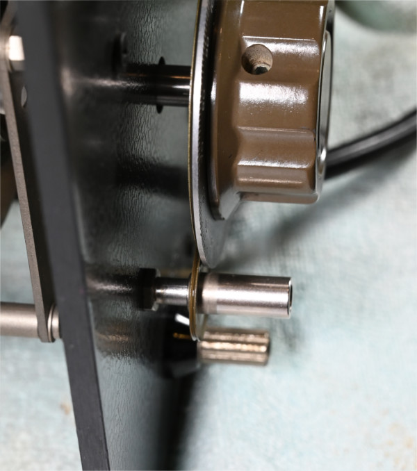
The fine adjust knobs on the capacitors should be serviced. The main knobs and fine adjust knobs should always be gently worked on and off as a pair. You don't want to do anything that would spring the mechanism on the small knob, or bend the disc on the large knob. I use a film of common #2 Teflon grease on the shaft of the small knob assembly and a film of Teflon oil on the friction drive discs. When the knobs are reinstalled, keeping them as an assembled pair, the fine adjust bushing shouldn't be up against the back of the shaft. It should rotate freely about 0.010" away from it.
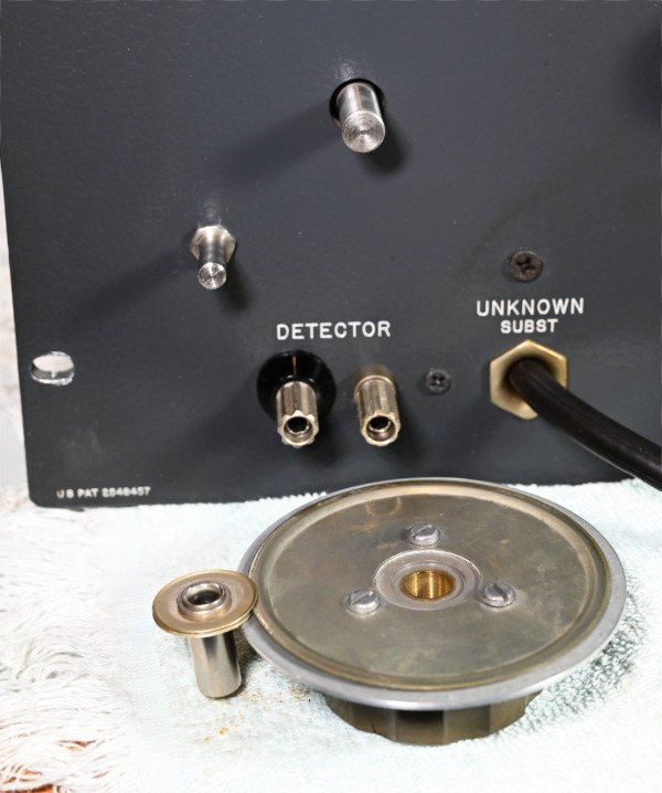
Here the knobs are being worked back onto the shafts. The scales on the knobs run 0-100. Both capacitors should be aligned such that the plates are fully engaged with the knobs at 100. Hold the edges of the plates with your fingers and adjust the knob rotation, then tighten the set screws. I use a trace of light plastic-safe oil (Superlube) on all screws, including the knob setscrews.
The complete manual is available on the IET website. The unit isn't difficult to use in direct mode, but you have to do several more balances than with the bridge alone. For substitute mode you really want to have the manual page handy!
GR 716-P4 manual from IET Labs
The cables are quite short and the only location for the 716-P4 is right on top of the 716-C. In my case this is a tight squeeze due to some bookcases, but it just slips in if it's angled back slightly. Each cable and connector is clearly labeled. The screw on each shield is ground, so goes to the chassis terminal on the 716-C.
You'll notice that the input cable consists of the standard GR 874 hermaphrodite connector, plus a second wire. Measurements are made between the center pin of the connector and the wire. The shell of the connector is the shield.
The basic procedure is to install the unknown capacitor and set the bridge to the approximate value and dissipation factor. The P4 is then set to coupling and the coupling resistors are adjusted for best balance. Then you set for guard and adjust the guard capacitor and resistors for best balance. Switch to bridge and balance the bridge. Work back and forth between guard and bridge until the deepest null is observed. At this point the bridge should display the value of the unknown.
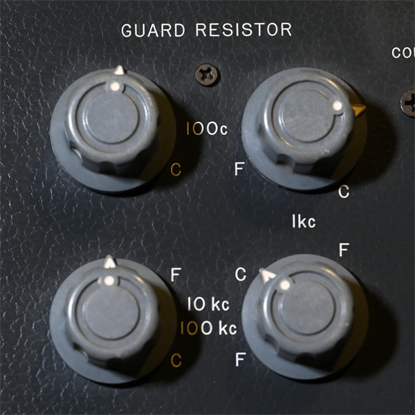
The guard resistors can be a bit confusing until you understand the labels. For each frequency there's a coarse and fine knob pair. Note the frequency labels and associated C and F in the photo below. C and F indicate which knob is which; they have nothing to do with the rotational setting. For 1kHz you'll use the upper and lower knobs on the right. The coarse knob is on top and the fine knob is on the bottom. For 100 Hz use the upper two knobs, coarse on the left and fine on the right. For 10 kHz and 100 kHz you'll use the lower two knobs. To keep things interesting, they reverse the coarse and fine. For 10 kHz fine is on the left and coarse is on the right. For 100 kHz fine is on the right and coarse is on the left.
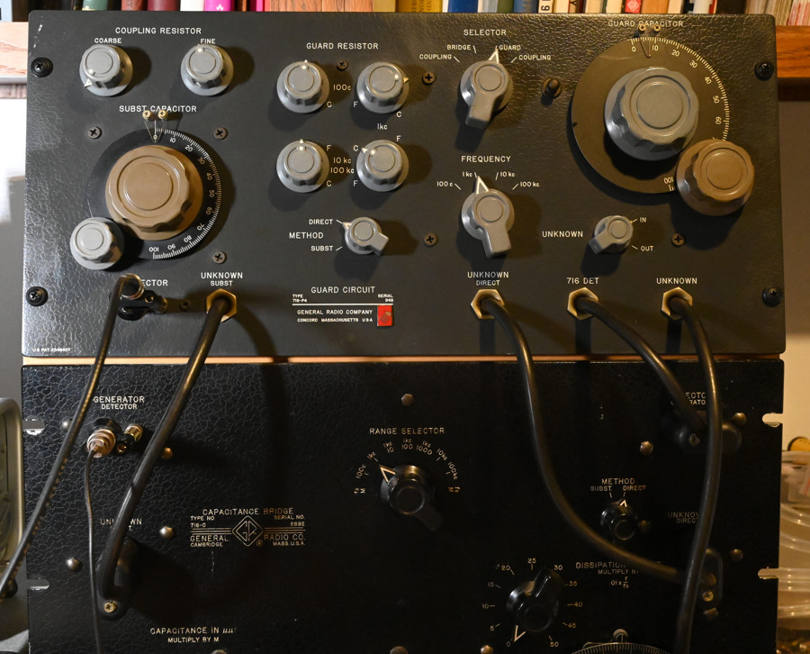
Here's my cleaned up 716-P4 connected to a slightly older 716-C.
C. Hoffman
last major edit April 30, 2023