
A well known weak point of the HP 8640B RF Signal Generator is the gear train connected to the frequency range switch. As you can see from the photo above, it uses one-piece spur and bevel gears. The gears are made of Nylon and over the years they tend to shrink and split around their brass hubs. The one-piece combination gears are the worst offenders, but the assembly also contains simple spur gears that are prone to the same trouble. Any of these gears can be replicated by silicone molding.
This process resulted in excellent quality replacement gears for my 8640B. Understand, however, that this is the first silicone molding I've ever done. Many decisions were made to increase precision and reduce the risk of failure, at the expense of more work in the form of more finishing operations. You may decide to do things differently, and there's nothing wrong with that at all.
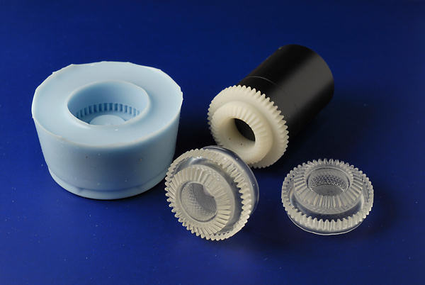
I apologise for not taking photos during this whole process, but the photo above shows the white master gear with a rod glued to the back, the blue silicone mold and some of the new cast gears.
The first thing one should do is a brief survey of the information on the web. Silicone molding is a popular and widely used process and there's a wealth of information, not to mention suppliers. Search on the terms silicone, RTV, RTV1000, TASK 9, molding, casting and urethane in various combinations. Learn about the different ways of making molds, as you will almost certainly modify this procedure, depending on your resources. Here's is my materials and equipment list, but don't give up too quickly if you don't have everything:
I chose RTV1000 from Eager Polymers as my mold compound. It's a 2-part RTV with a 10:1 mix ratio, so you'll need a small scale to weigh it. A double pan balance is handy because you can place a small plastic cup on each side and weigh directly. This material is simply amazing in its ability to capture details of a surface, stretch without tearing, and release the part without sticking. Because I've chosen to do the mold with an overhang, this material contributes greatly to success.
For the casting compound I used Smooth-On TASK 9, also purchased through Eager Polymers. This is a high tensile strength urethane with a 1:1 mix ratio (by volume, not weight). You should understand some things about these urethane casting compounds. They are not good for high temperatures, and TASK 9 will soften at about 131°F/55°C. That's not very high, but seems OK for the 8640B. I wouldn't use it in tube equipment or next to heatsinks. I was very skeptical of this material when it came out of the mold, as it seemed neither rigid or strong. Urethanes continue to crosslink for a very long time. Even though the "demold" time is listed as an hour, the part would be subject to warpage. Do not demold that quickly. Instead, cure for the specified 1 hour at room temperature, then transfer the mold to an oven. Bake it at 150°F for 4-6 hours. The part must be in the mold, or it could sag or warp. This will improve the mechanical properties tremendously without having to wait a week or more. Note that the data sheet properties are measured after a full week of curing, at which point the material becomes quite impressive.
The cast part can only be as good as the part you use to make the mold. For a gear to work correctly, there must be as little variation in the teeth as possible. When the 8640B gears age, they shrink. When they shrink around the brass bushing, the hoop strength is exceeded and the gear cracks, popping open in one or more places. You must eliminate this crack as completely as possible to use the part as a master. In my case, the rear-most gear (without the set screws) was the best candidate, as it had a slight crack, but not full separation. Pressing the bushing out would surely break it. I gently chucked up the gear in the lathe and bored out most of the bushing. When the bushing was starting to break through, I simply rolled the foil thin metal out with needle nosed pliers. This allowed the gear to relax and the crack to shrink to near zero. That's the white gear in the photo above.
My other gear (with the set screws) was split. It was an easy matter to put a small rod in the drill press and push out the bushing towards the flat side of the gear. The gear was then placed over the needle nosed pliers and the crack pushed open to about .010". A drop of cyanoacrylate glue was injected, and the gear immediately clamped closed for an hour. This gave me two very good gear masters, but I decided to use the first one so as not to complicate the mold with the set screw holes. If you have to use a gear with set screws, plug the holes with molding clay. Sand the back of the gear smooth and flat on 220 grit carbide paper.
There are many ways to make molds which Google will reveal. I wanted a simple easy to fill single cavity mold. This would allow degassing of the urethane, and would insure perfect alignment, since there was only one section. On the downside, the back of the gear has to be finished on the lathe.
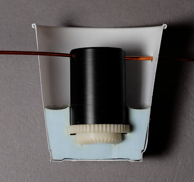
I cut a piece of Delrin to just under the root diameter of the outside spur gear (0.925"), and about 1.25" long. Delrin was chosen because it would release from the mold easily. In hindsight I should have made it 1.75" long. It was cross drilled at one end so it could be supported, and drilled through the center with a 1/16" drill for venting. This was glued to the back of the gear with "stick glue" from the office supply store. I like this for temporary bonds, as it dissolves in water. The Delrin rod was carefully centered by examining the distance to the root of the gear teeth on each side. Let it dry for a good few hours.
We now have an assembly that can be hung from the top of the 3 oz. plastic cup by placing a wire or rod through the cross drilled hole. You can see it in the photo above and the cut-away below. The gear should end up suspended about 0.5" from the bottom of the cup. I'll continue as if you were doing this yourself- hopefully that will soon be the case!

Using the scale, mix about 1 oz of RTV1000 in another plastic cup. Mix thoroughly and put the cup in the vacuum chamber. Pump it down to degas the mixture. It will foam up, and can easily overflow the cup, so bring the pressure down at a rate that keeps the material in the cup. A note about my vacuum chamber- I use a short length of 4 or 5" diameter schedule 40 plastic pipe. This is turned flat and smooth on each end. The base and lid are 1/2" thick Lexan, with the lid having a small brass fitting near one edge. For strength, don't put the fitting in the center! A simple flat ring gasket was cut from a sheet of rubber and is used both top and bottom. At this size, the stresses are very reasonable for the materials involved. Do not attempt a larger chamber unless you are experienced with vacuum design. My pump is an old Edwards Speedvac vane pump.
Pour the degassed RTV1000 into the mold cup, filling about 0.35" over the top of the gear. Put the mold cup in the vacuum chamber and repeat the degassing. Don't worry about the material wetting high up on the Delrin rod, as the thin film will be cut away later. You may never get all the bubbles to stop, but after a few minutes the remaining air will be negligible. Bring it back to atmospheric and allow at least 4 hours for curing. More is better.
Cut the cup in a few places, peel it back, and remove the mold and gear. Run a sharp knife around the Delrin rod at the surface of the mold and remove the thin skin from the rod. Now, the big event. Using your thumbs, carefully start pulling the mold away from the rod. Keep working it until you can see down to the top of the gear. Now, push the rod to one side and keep working around to get the gear over the step and moving up the bore. Walk it around until it's free of the mold. Remember this step because it's exactly the same maneuver you'll use to remove the finished parts. Inspect your mold. Look for voids, tearing, or other imperfections. With luck, it will be a perfect replica of the master gear.
Now we cast! Mix up a couple teaspoons (maximum) of TASK 9. The viscosities of part A and B are quite different, so you won't get equal quantities using spoon measures. Use a permanent marker on the plastic cup for the fill heights, and then fill to those. Mix quickly and degas. You only have 7 minutes! I cast in my cold unheated garage during the winter, so the pot life is a bit longer. In hindsight, this was a huge advantage. Now, bring the TASK 9 back to atmospheric.
Pour the urethane into the mold, filling about 0.2" past the gear area. Hint- I now place a tight fitting paper tube in the top of the mold so the urethane can bubble up without spilling. Put the mold in the vacuum chamber and degas. It will seemingly degas forever, but don't go beyond the time when the remaining urethane in the other cup starts to thicken slightly. Whatever air remains will be negligible. Bring it back to atmospheric and let it sit for 1 hour to cure. As described earlier, do not demold the part. Put the mold and part in a low temperature oven and bake at 150F for about 4-6 hours. This will greatly improve the properties of the part.
Now, using the same type of maneuver as before, pull the top of the mold sideways and separate the top of the part. Work your way around the mold until the gear is exposed and then walk it up out of the mold using your thumb to gently pull the center of the part to one side. Admire it!
I turn a simple brass bushing on the lathe. 0.423" OD, 0.2505" ID, 0.25" long. Rough up the outside with a very light knurl, a file, a grinder, or the method of your choice. Mix and put a thin coat of J.B. Weld epoxy on the inside of the gear, and the outside of the bushing. Slip it into place and cure. Warm it if you like to speed things up, but don't heat the gear excessively.
Your finishing method will likely vary, but here's mine: I chuck up the gear on the round back area left by the top of the mold- remember I carefully centered the Delrin rod on the master gear for a reason. I drill the urethane through the bushing with a slightly undersized drill, then ream with the same reamer I used to make the bushing. Now the gear has a well aligned hole all the way through.
In the old days of machining, taper mandrels were common. I jam the gear on a suitable tapered mandrel (these taper only a thou per inch or so), then chuck it up and face the back side to be flush with the bushing. I then pull it off the mandrel and touch up the back side on the 220 grit paper. The free rotating (rear) gear is now done.
Most people would make a one time expanding mandrel to hold the gear by turning a short piece of brass to 0.250", tapping the end, and slitting it with a saw. A flat head screw would then expand the mandrel to hold the gear for machining. If you don't remove the mandrel from the lathe, it will run perfectly true.
I prepare the next gear exactly the same way, then drill and tap the set screw holes. The gear is clamped in a mill vise with a short plug or ball in the front of the bushing, to prevent crushing the bevel gear portion. A 0.111" drill (#34) is deeply chucked so only a short piece is exposed, and a hole is drilled through the urethane only, at 0.157" from the back surface of the gear. This will cut into the spur portion of the gear very slightly, though less than my factory gears. A #43 drill is then chucked up and the hole continued through the brass. It gets hand tapped with a standard #4-40 tap. There are two set screws at 120 degrees from each other.
Rebuilding the range mechanism is beyond the scope of this write-up, so hopefully you took good notes and photos when taking it apart. A few hints. The small bevel gears that will mate with the new cast gears should be checked and adjusted. If they're tight on their axle, they should be opened up ever so slightly with a suitable reamer. If you don't have one, don't mess with them. There should be no significant slop, but excess friction in an already complex assembly, won't help things any. Mine had shrunk enough to be quite stiff on their axles, and required about 0.0005" of material removal to turn freely. The clips that restrain the gears should be adjusted so the teeth line up with the new gears and run smoothly. The last gear to engage and lock is the freshly cast gear with the set screws. Be sure you have good tooth engagement without excess friction. Use a magnifying glass. Poor engagement could result in stripped gears or other problems. Be sure to check the output frequency of your 8640B with a counter, as the front panel counter will be wrong if you don't get the knob/gear mechanism properly synced to the actual range switch module. The first time I reassembled mine, the front panel indicated 1 Mhz, but the actual output was 2 Mhz. I was off by one position. This was fixed by simply loosening the universal joint opposite the knob/gear mechanism, changing the setting by one range, then retightening the joint.
That's how I did it, but there's lots of room for improvement. I took certain paths because I have the equipment to deal with those choices, and valued precision over convenience. I also wanted to do this once, and then move on to other projects, like using the 8640B! For example, it may take experimentation and several trials to get a more complicated mold working. If you lack a vacuum pump, lathe, mill/drill, or some other item, there are still ways to do this. I'm guessing, but if the materials weren't degassed at all, the gear would probably still be serviceable. It might take rolling the mold at 45 degrees or so to distribute the urethane into all the teeth. It's probably reasonable to cast the brass bushing right into the urethane in one operation. Without a mill/drill, one could eyeball the set screw holes at a slight angle, avoiding the spur gear. The mold could be set up as a two part mold, avoiding machining of the back of the gear. I would recommend making new bushings as reusing the old ones limits one to very few new gears.
Good luck! I'll certainly entertain any questions, but I've tried to put just about everything I learned into this admittedly wordy document.
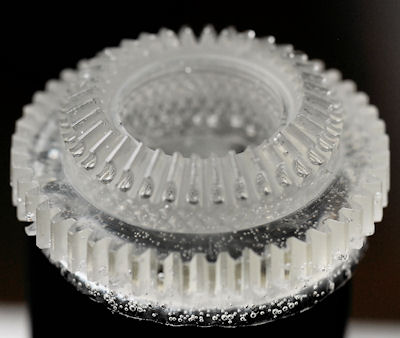
Experiments with non-degassed resin were unsuccessful. It might be possible to use a small disposable paintbrush to encourage the resin into the tooth area of the mold, but the part will be very prone to bubbles and flaws. A vacuum pump of some sort is really essential if a high quality part is to be made. Note that the sharp edges created by bubbles, which are essentially unfilled areas of the mold, quickly started to cut the mold on part removal. So not only do you get a substandard part, but the mold is quickly destroyed. There is almost no tendency for damage with properly degassed resin. Note the incomplete fill on the teeth in the photo below, plus all the bubbles!

Gear quality can be improved by changing the resin handling a bit. With the resin at room temperature, there isn't enough time for two degas operations, nor is there need for two. My new procedure is to roll and tape a paper tube that fits snuggly in the mold opening. I mix the TASK 9 and fill the mold, then insert the paper tube. That goes in the vacuum chamber and is pumped down immediately. The resin foams up the paper tube about 1.5", then settles back and "boils" for a bit. I don't think there's much of a problem boiling off resin components at low pressures for the times involved here, and best results seem to be obtained at pressures of less than 1mm of mercury. Most people won't have a gage with that kind of resolution, but don't worry about going too low. I hold the vacuum until the residual resin in my plastic cup starts to thicken, about 3-4 minutes.
It only takes a bit more than a teaspoon to fill the mold. You can't accurately measure the thick resin by volume in these quantities, and there's a lot of waste. I was not getting maximum mechanical properties of the resin when mixing by volume. Since one already has a scale for the RTV1000, it's wise to use it for the resin as well. The proportions are 115 of A to 100 of B by weight. Start with B and put one teaspoon in the plastic cup. Since B is the thicker part, you can let the spoon drip for a minute or two to avoid waste. Say you have 5.1g of B. Multiply by 1.15 and add 5.1 for a total of 10.965 grams. Add part A and drip it in until you have 10.965 grams. Mix quickly, fill the mold, install the paper tube and degas. Remove the tube and cure at room temperature for 1 hour. Bake at 150°F for 4 hours. The part should be very hard and have a slight amber color.
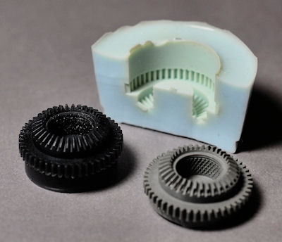
It's also possible to cast gears from other materials. Below is a gear made from J.B. Weld and another made from some generic clear epoxy with a black colorant. The J.B. Weld has too high a viscosity and the teeth didn't fully fill. Heating it a bit might help. My guess is the urathanes are still the best choice for proper mold fill and part durability. I cut the mold in half after it was pretty well worn out from sharp edges. It would have lasted far longer with the right degassed resins.

Additional 8640B reassembly info: Since the range assembly comes out from the bottom, my descriptions of up, down, left and right, will be as you see it (upside down), not as the instrument is normally used (right side up). Before disassembly, put the range knob in the 16-8 Mhz position (EXT2X straight up when the module is upside down)), and the deviation knob in the 160 kHz position (blank spot straight up when the module is upside down). Now, looking at the module upside down, with the switches in the described positions, the clear plastic switch wafer on the front left (range) will have one white slider button centered in the blank pie slide between the circuit board traces. The other button will be to the right. This disk should have three finger pairs. The clear plastic switch wafer on the front right (deviation) will have one white slider button straight down and one to the right, pointing at a mounting spacer. This disk should have two finger pairs.
The rear disk is a bit more difficult. If you flip the module over so the shafts point away from you (it's right side up now), the disk should have one white button within the pie wedge, just kissing the left edge. The other white button will be outside the pie wedge, to the right. The last step will be to engage and lock the new twin gear with the set screws. Do that and check the rear disk. Install the range knob and click it a few positions. The contacts on the rear disk should hit the center of the smaller trace segments. If not, readjust the gear engagement. For maximum reliability, one set screw should always bear directly against the shaft flat. Yes, a picture would have been nicer, but I failed to take one when I reassembled my unit.
C. Hoffman
last edit November 26, 2011