The Sansui 2000x is a good sounding and popular vintage receiver. The 2000A is almost identical and most of what's here applies to that unit as well. The 2000 is also similar, but lacks the handy plug-in power amp board. Unfortunately, one of the small signal transistors used in various places has a history of becoming noisy. It's the notorious 2SC458LG. Some units were built with 2SC631 or 2SC632, and those are also prone to noise. There are various commonly available parts that can be used for replacements, but I can only vouch for parts I've measured and tested. On-line you'll find KSC1845, 2SC1815 or 2SC1815L, 2SC1775 and 2SC2240 suggested. In the past I've used 2N5088 with good success, but recently tested the KSC1845 and found it a bit better. The higher gain ranges are preferred. Also acceptable are 2N4401, 2N3904 and MPS-A06, any of which I wouldn't hesitate to use, though the 1845 and 5088 will have higher gain that better matches the original 458. The common 2N2222 has about twice the noise as does 2N3416, so don't use those, even if you have a junk box full. The only caution is that the original part has a pinout of ECB and many common plastic transistors will be EBC. You have to be careful to get the right leads inserted in the right holes during replacement. Note that the KSC1845 has the same pinout as the original and drops in with no odd bending, so KSC1845 is the preferred replacement, though my photos and descriptions here will still show the 5088.
The 2SC458LG is used in the tone control stages, the power amp stage and there's even one in the multiplex section, for a total of nine devices. I suggest you change all of them except the multiplexer (unless you can do a tuner alignment) as none are very difficult to get to, the parts are inexpensive and the failure rate is high. People tend to be paranoid about capacitors in vintage gear, and less so about semiconductors, but your 2000x is far more likely to have the latter than the former.
Speaking of capacitors, none of the Elna electrolytic caps in my particular 2000x had any problems with value or loss tangent and none had visible signs of distress, so I left them alone. Since you'll have the unit open on the bench, if you really feel the need to replace electrolytic caps, now is the time to do it. Use good quality parts. I use slightly higher voltage ratings because they have lower dissipation factor. You'll note Sansui already did that with the 50V coupling caps on the tone board. I'd also suggest using a low leakage series for the coupling caps. Don't use a Silmic II for the big filter on the tone board, as it probably won't fit back in the chassis! My only caution is that you make changes and do replacements one section at a time, testing the receiver between each session. It's far easier to troubleshoot a problem if you know it occurred on an individual board, rather than the entire unit.
After doing a bit of research and testing various ideas on the bench I came up with the mods outlined below. They're well accepted features of many designs, and so should be relatively benign. They're also easily reversible. Naturally I cannot accept any liability if you decide to do them and wreck the receiver as a result of your errors, my errors or for any other reason. You need to look at the receiver and the schematics and determine for yourself if these mods are suitable and applicable and that you're capable of doing them. You must have a schematic and layout to complete these mods. You'll also need a DVM that can resolve 1 mV on its lowest DC scale. A scope and signal generator are nice but not required.
If you can't take full responsibility for modifying your equipment, and have sufficient electronic knowledge to do so safely, please use your "back" button now. This page is not for you!
My Sansui 2000x power section needed some repairs due to above mentioned noisy input transistors and a bad Vbe multiplier transistor, so I had it on the bench for service. I don't know how well these circuits worked when they left the factory, but by modern standards the small signal distortion is excessive and contains rather undesirable harmonics. It's a wonder the 2000x has as good a reputation as it does since the power amp section wouldn't have been considered particularly good in its day, much less now. My guess is the fantastic tuner section more than makes up for any other shortcomings.
My 2SC458LG transistors probably weren't terrible but I thought they could be better. Make up some RCA shorting plugs and install them in the power amp inputs. Power up and listen right at the speaker. You should near nothing or very close to nothing. If you hear hiss or hiss with some erratic low frequency variation, the input transistors might be the culprits. See the info on replacements up above. Being quite a ways downstream in the circuit I don't think the noise performance of this transistor is absolutely critical compared to some others, but since you're getting low noise parts for everywhere else you might as well use them here, just as the factory did.
Sorry to say, but transistors of a given type may still vary in noise performance. If you hear excessive noise or variations like popcorn noise, troubleshoot further and even change the transistor again. The very first 5088 I pulled from the bag had a popcorn noise problem. The transistor numbers listed above were not selected by data sheet values, but by actually testing for noise between DC and 30 kHz in an exact copy of the Sansui power amp circuit.
The replacement part probably won't have the same pinout as the original. The board is laid out ECB, not EBC like most TO-92 plastic parts. You may have to bend the leads in an unnatural position. Be careful to get the pinout correct- it's printed on the circuit board. Use sleeving to insure that the leads can't short together because they have to be bent very close to each other. Or, use the preferred KSC1845 as it will drop right in.
The tone amp feeds the power amp directly and it or some other circuit may be contributing noise. If you install shorting plugs on the power amp inputs (pull the jumpers) and put your ear next to the speakers, you should hear almost nothing. With the normal jumpers in place you'll probably hear a bit of hiss. An erratic hiss with low frequency components usually means there's a noisy transistor somewhere, most likely in the tone amp board. Important- wait until the amp fully discharges when installing or removing the shorting plugs and jumpers or you'll get a nasty blast of speaker-wrecking hum!
To reduce the noise a bit more, change the 560 kohm carbon film resistors used for R803 and R823 to metal films. The other base biasing resistors R802 and R822 (150 kohm) don't affect the audible noise level but I changed those to metal film on general principle. Changing the resistors won't accomplish much in normal operation with low impedance sources, but reduces the open input noise noticeably. It's specsmanship so if you don't want to change the resistors there's probably no significant penalty unless you use the power amp section alone, driven from a higher than normal impedance.
The 2SC281 is used in the Vbe multiplier. Almost any small signal device will work here. MPS-A18 is a published substitute. I used 2N3416 as the curve family matched the original parts almost exactly. Same notes on pinout and sleeving as above. Change only if it fails, as mine did, but change both channels if you do. Be sure to replace the copper heat transfer piece that couples the Vbe multiplier to one of the driver transistors. Put a little silicone thermal grease inside so the transistors make good thermal contact.
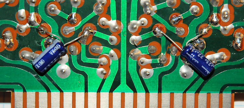
Almost every amp uses a cap across the Vbe multiplier to insure good high frequency performance- except this one. Install an electrolytic across TR803 and another across TR808 (the two 281s). The value isn't critical and you'll see everything from 0.1 to 50 uF used. I used 22 uF / 25 VDC. It never sees more than a few volts. Positive to the collector, negative to the emitter. These can be small radial lead caps placed against the rear of the board. Sleeve if needed. They have to be small to clear the metal cover. They look like this:

The quasi-comp output can be improved by use of a Baxandall diode. This improves the match between the positive and negative halves of the circuit, preventing a distortion spike at the crossover. The trouble with an unmodified quasi-comp output stage is that increasing the bias isn't very effective at improving the distortion performance the way it does with a full complimentary output. The Baxandall diode makes it very close.
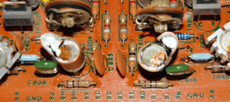
Remove R817 and R837 (4.7 ohms). Replace them with a parallel combination of 100 ohms and a diode. Use a standard 1 amp rectifier of 50 volts or more. If you have a fast one, so much the better but don't use a Schottky. That would defeat the purpose. 1N4001 or higher is fine. The bands of the diodes point to the outer edges of the board- don't mess that up! Check it twice and then check it again.
The above mod and/or changing the bias transistor will shift the bias adjustment range lower so we have to get it back again. Change R814 and R834 (1.5 kohms) to 1.0 kohms. Set the bias pots full CCW. You can see both the diode / 100 ohm mod and the 1 k mod below. Note that both diode bands (under the blue 100 ohm resistors, 1000 = 100 ohms) point away from the center of the board:
Note- adjusting the offset voltage, i.e. the clipping symmetry, will change the bias current. Adjust the offset (upper pots) first! Adjust the bias current second, though it's described first in the following paragraphs.
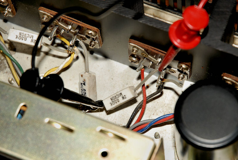
With no signal, and at room temperature, bias the amp (VR802 and VR804) for 11-12 mV across each of the emitter resistors R842 and R845 as shown below. These are the big 0.5 ohm resistors soldered from the outputs directly to the chassis tab behind the circuit board. The adjustment will be a bit touchy. Monitor the voltage for stability until you're sure it's staying within the limits. This will give you 22-24 mA per output pair, as opposed to the factory setting of 15 mA for the whole circuit of each channel. It's still a very low dissipation and won't cause much heating of the output stage. This current value was a compromise between lowest distortion and fear of too much dissipation- it's very conservative. Since the amplifier doesn't sense on the heat sink, the bias current will vary quite a bit with drive level and temperature. Driven at full power until the heat sink is about 160 F, just uncomfortable to touch, the bias will be at about 30 mV (60 mA) when the signal is removed. It will quickly fall from this value and the heat sink will cool. Any tendency to increase when signal is removed means that thermal run-a-way is imminent and power should be removed until the cause is found.
Speaking of hot amplifiers, my output transistors were very poorly coupled to the heat sink. There was barely a trace of clear grease on the parts and the usual mica insulators. It was obvious that the tops of the cases were running way warmer than the heat sink. You should probably pull the outputs, clean and regrease everything, sparingly, or do what I did- use some nice high performance Sil-pads. The gray ones are OK, but they also have versions with much higher thermal conductivity.
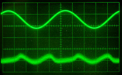
Rather than tell you, I'll show you. Here's the output of the distortion analyzer for a 1 kHz signal and 1 Vrms into 8 ohms and no Baxandall diode installed. The signal is on top and the distortion residual is on the bottom. The distortion level was about 0.07%. The analyzer scales the output so look at the character and high frequency harmonics rather than the amplitude.
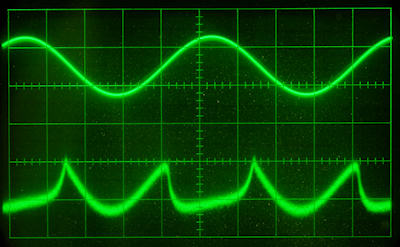
The trouble with the quasi comp output is that increasing the bias does little to improve the situation above. Now we'll add the Baxandall diode. Immediately the THD goes down by about half for the same bias current, but look at the improved character of the residual. The higher frequency harmonics are mostly gone. More bias current would improve things even more, but at the expense of dissipation and thermal stability.
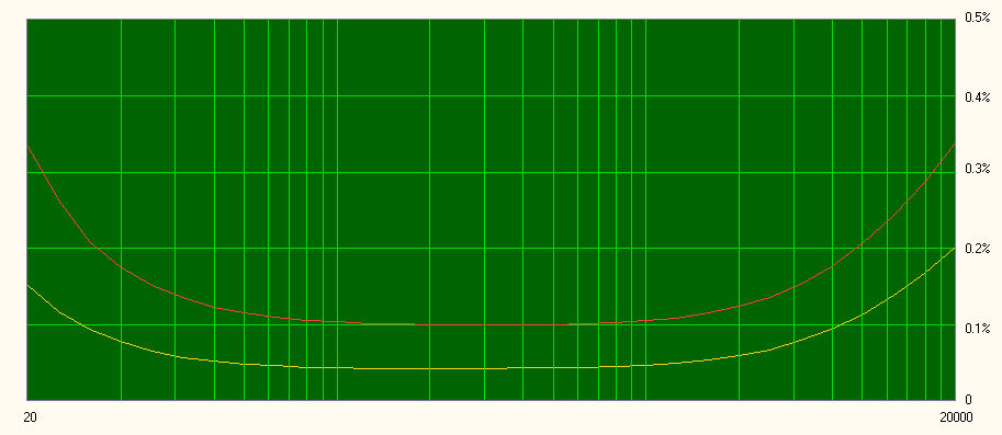
Here's a plot showing the before and after THD of the power amp section. It's done at a very low level, which is where crossover distortion is at it's worst. The modifications basically cut the distortion in half, and you can hear this as an improvement in clarity, particularly in the low end, where the 2000x can be a bit muddy. You may actually perceive this as a slight reduction in bass, but it goes as low as ever, just with better resolution.
Though the amp is specified at 39 watts per channel, Sansui appears to have fudged it a bit by giving the single channel power. The amp isn't really capable of 39 watts per channel with both channels driven because the power supply will sag slightly. More like 32-34. On a good day. With the wind to its back.
The manual directs one to set the offset with a single channel driven to full power. This would make the single channel power output look very good and 39 watts is no problem if you do that. I can even make a case that by setting the offset with a single channel driver it may more closely approximate what happens when both channels are driven with a music signal. The music won't have a large average power and won't load the power supply as much as a continuous test signal.
If you don't have a scope and signal generator to set the clipping levels, it's probably sufficient to simply look at the DC voltage on the output, before the output coupling cap, and set it to 1/2 the loaded supply voltage, or about 30 VDC. This can be done at either end of R841 and R844. The values are so low that it doesn't matter which end you grab. (new info- after looking at the clipping with music and with a pink noise source, setting the voltage to 30 VDC with a 120 VAC line is quite accurate.)
The noise is now about 101 dB down from the 30 watt amplitude when driven by a low impedance generator. That's pretty good but in real life you'll still be able to hear a bit of hiss from the speakers if you put your ear close. There will also be a slight background hiss when using headphones but because the crossover distortion has been improved the overall experience should be far better.
During simulation I noticed one other thing. The low frequency response is highly dependent on coupling cap values. I don't recommend changing the 0.22 uF input cap, though on the surface it seems like a sensible mod. The low frequency response of the amp is a bit load dependent as is and changing the input cap can easily make it worse or put a wiggle in the response curve. The actual response will depend on the speaker impedance, but the effect isn't large.
See Doug Self's book on amplifier design for more details on the Baxandall diode and Bob Cordell's book for more info on Vbe multipliers.
The tone board feeds the power amp and it uses six of the notorious 2SC458LG transistors. Those almost certainly need to be replaced and there are various aluminum electrolytic capacitors that might be getting tired, though the Elna parts in my unit were all fine. If you're the paranoid type you should probably replace them as long as the board is exposed for service.
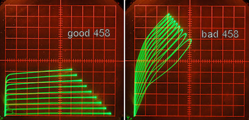
My 2000x sounded good, but it seemed like the channel balance wasn't stable. It also seemed to have less definition than it should have. When the old transistors were checked the reason became clear. Four of the six transistors had developed leakage and unstable Hfe, not to mention excessive noise. It's actually a wonder the circuits worked as well as they did. Below are curve families for a good 458 and a bad one.
The tone board is easy to service. Pull off the volume, balance and tone knobs. Remove the bottom cover of the receiver and then the two screws near the front edge that secure the tone board. Carefully manipulate the wires as you flip the board over and get access to the component side as shown below. You can see the six transistors I've already replaced.
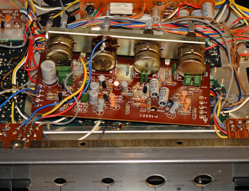
The 2SC458LG has a BCE pinout. I replaced them with the 2N5088 which has the common EBC pinout. Be sure to look up the pinout for your replacement device and install it accordingly. The board is clearly marked but take your time and double check your work. Here's a closeup of how to install an EBC part.

Try to do several things each time you flip the board. This will reduce stress on the wires. For instance, unsolder all the transistors at the same time once you've identified the pads, then solder all the new ones.
The 2SC458LG simply didn't age well. It happens now and then that semiconductor processing or packaging isn't what it should be. Chances are you'll notice greatly improved sonics after installing fresh low noise parts in both the power amp and the tone control circuit, probably more so than any other change you could make.
New info- later units used 2SC632 instead of the 458s. The drivers may be 2SC959 and 2SA606. The outputs may be 2SC1111. Those all appear to be improvements, though the 2SC281 is still used for bias. I've seen the 2SC281 fail on occasion, but not often enough to say whether it should be routinely replaced. Check the noise level on the 14 and 25 volt regulated supplies. Sometimes the zeners can get noisy. They run at low currents and any small general purpose zener should be able to replace them.
When you put the tone board back, you have to hook in the top, opposite the two screws, or the knobs will be at an angle and hit the front panel. There's also a risk that the board will hit the bottom cover. Hold the board so the mounting piece with the two screws is slightly away from the front lip, work the top in by tilting the board down, then bring it into place and install the two screws.
The RIAA equalization gets switched in and out, and all signals go through the RIAA board. Be sure to replace the two white Elna CS capacitors (1.5 uF) with low leakage electrolytics or films. They're often bad. Though listed in the parts list as tantalums, they're more likely a solid aluminum type. 2.2 uF should work fine, but not larger. The transistors and other caps are usually fine, though some suggest replacing them as well. I'd advise caution per the following.
The RIAA equalization isn't very flat, with a bit of a hump in the middle and some bass rise. The shape of the low end will change depending on the gain of the 2nd transistor. It should probably around 200, so the high gain KSC1845 may not be a good choice for that location. It should be OK for the 1st position. The 47 uF capacitor also gets involved with the shape of the low end, and a case can be made for increasing it. Remember that anything done also has to work in the flat configuration used for the tuner and AUX inputs. More on this when I do more tests and simulations.
The following mostly concerns alignment. Alignment really deserves its own page, but until then this seemed like as good a place as any. The 2000x uses a traditional tuned transformer FM IF amplifier, meaning that to get the IF waveform correct you need to sweep it and adjust six transformer slugs. Don't even consider touching this unless you have a sweep generator with markers and a bit of experience. You'll also need an FM stereo stereo generator and, though you can probably get somewhere close without it by sweeping, a THD analyzer.
The basic procedure in the service manual is better than most, though there are a few omissions and label errors. In no particular order, here's a handy list of things to be aware of. Note that the 2000a is essentially identical to the 2000x.
The MPX board is responsible for splitting the composite signal out of the IF amp into the two stereo channels. It can be a bit intimidating at first, but if you look at the schematic, it breaks down into two circuit paths. The path on the top contains tuned amplifiers for the 19 kHz pilot signal, a doubler to get 38 kHz, and the demodulation/filter section. The lower path basically amplifies the signal and uses it to turn the stereo light and the 38 kHz amplifier on and off.
You can troubleshoot and repair the MPX board quite easily. You can almost align it with just a scope, an audio signal generator and a frequency counter. Unfortunately, the very last step requires FM stereo RF generator and I don't know any good way around that. If you adjust any of the transformers, the last step is essential. If everything is otherwise working properly, aligning the MPX board consists of seven steps and can be done in just a few minutes.
Job done- maybe. If the preceeding didn't get you good stereo, the MPX board might need some service. Be warned that most MPX boards are F-1190-2, which is slightly different than the F-1190 in the available schematics. The F-1190-2 uses discrete filter parts at the output, rather than the small potted modules shown on the schematic. Other than that, it's nearly identical, save for the mismarked T401 and the 4J test point not being connected where the schematic claims. AFAIK, go by the cap polarity markings on the board, not manual layout diagrams, at least one of which is wrong for one version of the board.
The board can be a nightmare to troubleshoot until you understand the signal path and how to fool various stages to locate the trouble. Then it's pretty easy. There are a couple known trouble spots, so we'll hit those first. The input transistor is the notorious 2SC458LG, though it's a lower gain group (B) that seems less trouble-prone. It's specified for an hfe of 100-200. Later units used 2SC536 there and for the other NPN locations. Almost any small signal NPN with an hfe of about 200 will do the trick. I don't know if higher gain is a problem, but if it is that would rule out the popular KSC part that's often used as a sub. The next trouble spots are the two 0.022 uF ceramic disk caps, C418 and C419. They can develop subtle DC leakage that will prevent turning on the 38 kHz amp, not to mention the stereo light. This is a difficult problem to find if you aren't aware that it can happen. I replace them with small 0.022 uF films but any ceramic is also fine. Finally, there are several aluminum electrolytic caps. By now they're near the end of their lives so replace them with like parts of the same or slightly higher voltage.
Troubleshooting the signal path is easy up to 4J. If you have the expected signals up to that point, but no 38 kHz at 4H, try shorting the collector of TR406 to ground. Be sure the front panel input selector is set to FM Auto. If that suddenly lights the stereo light and gives you 38 kHz, the problem is likely in the lower control circuitry. Work your way backwards to see which stage is at fault. You can use a 10-20 kohm resistor to pull the base of TR405 to ground. If that turns on stereo, the problem is ahead at TR404 or the associated circuitry. Check the 1.2 megohm resistor. It's probably a composition and may have drifted. Check those 0.022 uF ceramics. You can try turning on TR404 with that same 10-20 kohm resistor to the supply (R422, the 47 ohm resistor in the middle of the board is a handy source of voltage).
FWIW, I now routinely replace both 0.022 uF caps with small films, and the 1.2 Mohm resistor with a metal film.
C. Hoffman
last edit July 9, 2017