Metric threading using a lathe with an inch lead screw isn't difficult, but instructions that cover the finer points are few and far between. It's a metric world and I now cut more metric threads than anything else. Chances are, if you're not cutting metric threads now, you will be sooner or later. My guess is sooner. With just a few extra gears you can cut any standard metric pitch on your small Logan, Southbend or other quality lathe. The following explanation may seem a bit tedious and repetitive, but a solid understanding of the basics will help you solve any problems that might arise, for any lathe, gear train or pitch.
The most common lead screw is 8 TPI, a pitch of 0.125". That's 3.175 mm, not a terribly convenient number from which to derive the standard metric pitches. The purpose of metric transposing gears is simply to scale that pitch into a more useful value that can be divided or multiplied, using common gear ratios, to get the standard metric pitches.
The traditional pair of transposing gears have 127 and 100 teeth. The lead screw pitch, 3.175 mm, divided by the ratio of those two gears, 1.27, gives us 2.5 mm, a much easier number to further divide or multiply into standard metric pitches. The important thing to remember is that using metric transposing gears allows you to treat your inch lead screw as a metric lead screw. The rest of the gear train simply multiplies or divides that new pitch value to get to the desired pitch. If you think of the transposing gears and lead screw together it avoids having to include the specifics of the conversion in every gear calculation.
A simple example will reinforce the concept. You've installed the metric transposing gears and now think in terms of having a 2.5 mm pitch lead screw. You want to cut a 1.0 mm pitch thread so you need some gears in the path between the transposing gears and the lead screw (or spindle, depending on where the transposing gears are installed) with a ratio of 1:2.5. A 16 and 40 tooth pair would do the job (as would various others having the same ratio). If you have a lathe with a quick change gearbox, the same rules apply. You still need an overall 1:2.5 ratio, using some combination of external gears and the ratios available within the gear box. I'll cover QC gearboxes in more detail later, but for the moment we'll assume a simple change gear machine with no gear box.
The traditional 127 and 100 tooth transposing gears are big and expensive. Worse, they usually won't allow the gear cover to be closed, increasing the chance of damage from metal chips and exposing people to the hazards of an open gear train. Make no mistake, open gear trains are extremely dangerous. They will pull things in, destroying both object and gears. Think injuries and amputations. Open un-guarded gear trains are never allowed in industry and a company would be heavily fined by OSHA for allowing such. If you use a gear train that doesn't allow the cover to be used, fabricate a suitable guard to protect yourself and others. It may seem overly cautious, but you should also unplug the lathe whenever you're working on the gear train.
The next issue is the banjo, the frame that holds the gears and allows their relationship to be adjusted. With the large transposing gears you may need an alternate or even custom banjo. Everything is lathe dependent. Some lathes accommodate these gear trains with little trouble. Others, typically the smaller machines used by hobbyists, require some ingenuity to convert. One could, of course, obtain a metric lead screw, but it's far easier to swap gears than lead screws.
The 127 and 100 tooth gears are the smallest gears that offer an exact metric conversion. If you were making lead screws or micrometer screws, those would be the gears you'd choose. Obviously you'd also need a perfect lead screw with no wear. The reality is that some slight error is tolerable; in fact it's unavoidable. There are other gear combinations that offer a more convenient metric conversion, albeit with a tiny error.
A common metric transposing pair is 47 and 37 teeth. Compared to the perfect ratio of 1.27, these gears will give you 1.27027027... That's an error of 0.021%, which is only 0.0026" per foot. For any normal length thread you'd be hard pressed to measure the error, much less notice any functional difference. In return for this small compromise you get a pair of gears only a few inches in diameter. They'll fit within the factory gear cover and the cost will usually be lower.
The smaller pair of gears also lend themselves to DIY fabrication if you have a mill and dividing head. Unless you're cutting very coarse threads, the forces on the gear train are low. Because of this, I make my transposing gears, and any other change gears I might need, out of Delrin or a generic equivalent. It's easy to cut, the cutters last forever and I've never seen any significant wear in the finished gears. My guess is that they'd even stand up to moderate production use with little trouble.
Another possible pair is 80 and 63 teeth. The ratio is 1.26984, an excellent match, but the gears are still quite large and may not fit inside the gear case. They may be a good choice in some situations, but as the gears get larger the exact match of the 127 and 100 tooth pair makes more sense.
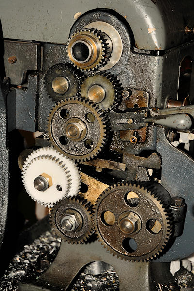
If you limit yourself to the transposing gears and the standard change gears that come with most lathes, there are quite a few metric pitches that can be cut using simple ratios. They are 0.75, 1.00, 1.25, 1.50, 2.00, 2.25, 2.50 and 2.75 mm. Simple ratios also allow a variety of coarser threads but you'll rarely need them. For finer threads and for in-between pitches you'll need compound gearing- another pair of gears to increase the division ratio. Here's a photo of a simple ratio set up to cut 2.00 mm pitch threads. Notice that spacers have been used under both the idler gear, which can be any number of teeth, and the screw gear. These are one gear thickness, so a small spare gear can also be used. The gears are thus in what I refer to as the outboard position. Move your mouse over the individual gears for more details.
Here's the 2 mm pitch thread cut on a short stub to prove out the gearing above.

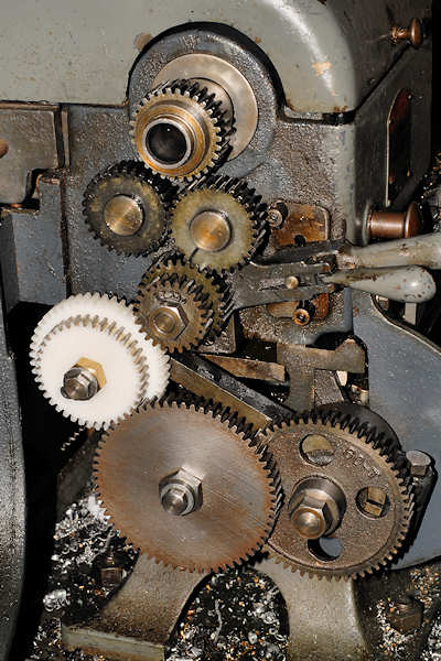
You'll often come across very fine metric pitches and somewhat odd non-standard metric pitches. Most of these can be cut by adding another pair of gears to create a compound ratio. As an example, a 0.5 mm pitch requires the 2.5 mm lead screw to be divided by 5. Even with the smallest stud gear of 16 teeth, that would require an 80 tooth lead screw gear. That is, in fact, the Logan recommendation for my lathe, but an 80 tooth gear is not part of the standard change gear group. Instead, I do it with a compound ratio. 24/60 and 32/64 gives 768/3840 or 1/5, and those gears are part of the standard change gears. Here's a photo of the compound setup to cut 0.5 mm pitch threads. Here only one spacer is used and it's on top of the screw gear, putting the gear in what I refer to as the inboard position. Move your mouse over the individual gears for more details.
If you have trouble getting clearance or engagement between gears, you can sometimes swap positions to improve the situation and keep the same ratio. Consider the above gearing where (24/60)*(32/64)*2.5 = 0.5 will also give the correct answer if you swap the numerators (or denominators)- (32/60)*(24/64)*2.5 = 0.5 Thus you can swap the physical gears as needed if it allows better engagement or clearance.
Though a great time saver for cutting inch threads on an inch lathe, a QC gearbox is an added complication for cutting metric threads. Only some of the ratios will prove useful and you'll still have to change the gearing ahead of the gearbox to get the standard metric pitches. Because my lathe doesn't have a gearbox, this section will be more of a quick overview than a specific how-to.
Gearboxes are implemented in several different ways, with different external gear ratios resulting in different internal gearbox ratios. Some switch all ranges within the gearbox and others shift both internal and external gears to change ranges. I wish I could offer more specific advice, but it may come down to simply counting external teeth and then calculating what the internal ratios must be to achieve a given TPI. With that info, working out the metric pitches is reasonably easy. The spreadsheet described below should prove helpful, especially if your QC gearbox is the same or similar to the Logan arrangement.
This is probably a good time to mention that not all lathes have a 1:1 tumbler/reverse gear setup. If there's an additional reduction there, it has to be figured in. The transposing gears might be 127 and 50 teeth, rather than 127 and 100. Fortunately most common Logan and Southbend lathes are 1:1. There are also lathes that don't maintain the same diametrical pitch gear system throughout the whole gear train. This can be a space saver as it allows higher tooth counts with smaller diameter gears. Sherline uses this to good advantage. Regardless, any lathe can be figured out by counting gear teeth and the input vs. output revolutions of the QC gearbox, if present.
Ideally your lathe manufacturer has supplied recommended gearing configurations for various metric pitches. If that information isn't available, and your lathe has the very common 8 TPI lead screw, I have a spreadsheet that should help you. It contains preworked tables for 8 TPI, along with worksheets for thread data and custom ratios, so you should be able to generate complete gearing tables for any lathe and any lead screw, with or without a QC gearbox. Dividing head calculations and some quick spur gear design utilities are also included should you desire to make your own change gears.
It's repeated everywhere and I believed it for too many years. It's really simplified advice for the unskilled neophyte and is only a half truth. What is true is that you can't lose track of the synchronization between the lead screw, gear train and spindle. What is also true is that you better learn how to release the half nuts or you'll never be able to thread cleanly to a shoulder. There's also a risk of damaging the threading tool as it hits the metal build up where the spindle stopped on the previous cut.
When cutting inch threads with an inch lead screw you keep track of synchronization with the lead screw using a thread dial. The thread dial can rotate any number of times and as long as you engage on the same number, or even fractions for many threads, the synchronization will be preserved and the cutting tool will correctly track the thread.
With transposing gears in the gear train this simple relationship is lost. If you lose the position of the half nuts on the lead screw, all is lost. The thread dial would have to rotate many turns to reach the correct starting point, and you have no way of knowing where that is. Thus the ancient and unquestioned advice never to disengage the half nuts.
I first saw this technique described in a post on the Practical Machinist forum. It's so incredibly valuable I can't believe it isn't more widely described.
If you watch your thread dial at normal threading speed it will turn at a slow rate. Think about how annoying it is to have to wait for it to "come around" for each pass when doing normal inch threading. The point is, you have quite a bit of time before the dial goes all the way around and you risk losing track of the starting point. The coast-down time of the lathe is almost always less than a turn of the thread dial. On my Logan it's less than 1/4 turn.
Let's say you're threading towards the headstock, up to a shoulder. You approach the shoulder and open the half nuts at the appropriate moment. The carriage stops. You then immediately shut off the lathe and back the tool out 1 turn. While the lathe coasts down, the thread dial continues to rotate, usually less than 1/4 turn. Now throw the switch to reverse. Everything runs backwards, including the thread dial. When it reaches the number where you were threading, re-engage the half nuts. The carriage will now travel away from the shoulder towards the start of the thread. When the tool clears the thread, shut off the lathe. Return the tool to the correct cutting depth plus the cutting increment and make another pass in the forward direction. It's not terribly difficult if you keep your wits about you; here it is in list form:
It's easy to make mistakes even with standard inch threading, and you now have a couple more things to remember. You should practice the above technique using an imaginary shoulder- just thread to a certain point and stop. Do this until you're confident in the process. You can pick up a piece of white schedule 40 PVC pipe at the local home store for practice material. Something around an inch is suitable. It's inexpensive and takes a nice thread if your tools are sharp. You can also bore it to get a clean round ID and use it to practice inside threads. Don't hang it more than a few inches out of the chuck, lest it grab and jam up the works.
It all depends on the degree of control you need. If you have to thread to within 0.002" of a shoulder with a coarse thread, you'd better be cutting at a snail's pace. Just for reference, when I cut a 0.5 mm pitch thread to a shoulder, I run the spindle at my lowest normal speed without the back gear. That's about 200 RPM. Any coarser than 0.75 mm and I'll switch to back gear and go slower. Run at a speed where you're not in a panic, even if that means some lost time returning to the start.
There are endless debates about the best way to cut single point threads. The following is considered a standard and you should at least know how to do it correctly, even if you generally use some other method.
Loosen the fastening screws for the compound and rotate it so the feed handle points directly at you. The compound will be parallel to the crossfeed. Look at the degree markings and note how they chose to number it. Ideally this position will be zero, but some lathes call this 90 degrees.
Rotate the compound counterclockwise (CCW) exactly 29° and lock it down. Some people use 29.5° and that's OK too. You want just a bit less then half the thread angle, never more. If your compound started out at 90° it should now read 61°. If it started out at 0° it will now read 29°. Unless they dreamed up some other way to mark it, but the key is pointing the handle towards your belly button, then going 29° CCW.
Set the compound feed to mid travel and zero it.
The crossfeed is now used to bring the tool tip just to contact the OD of the part to be threaded. That setting becomes the reference for each pass.
For each threading pass, feed the compound by the desired increment. At the end, back the crossfeed out by 1 turn so the tool clears the work and the carriage can return to the beginning. Before the next pass, turn the crossfeed in by 1 turn, exactly to the original setting. Increment the compound by the desired increment and make the next pass. In this way you only have to remember the crossfeed zero setting, and increment the compound until the thread reaches the correct pitch diameter. Measure this with wires or a pitch mic.
If you know the geometry of your threading tool, you can calculate the plunge depth at 30°, but the exact width of the flat at the tip is rarely known to sufficient accuracy, at least by the hobbyist. It's far better to simply check the thread fit as you go. The width of the crest of the thread will also provide a good indicator of how far you have left to go.
Gears are designed to operate with a certain amount of backlash. When you adjust your gearing, there should be a slight rotational play, ideally about 0.005" at the teeth. Run the gears all the way around by hand to be sure there aren't any tight spots. Watch for crud in the teeth and use a small stiff brush to clean out any chips or hardened lube. On the subject of lube, the last thing I want is a coating of dirt-collecting grease on my change gears. All that's necessary is a small squirt of way oil every now and then. If you have gears that are constantly engaged, a very light grease may be appropriate, especially if the maintenance interval is irregular. If you can remember to oil them periodically, I believe oil will keep things cleaner and have less tendency to attract stray metal chips.
Clean and oil the ways and leadscrew with way oil just before threading, then run the carriage over the area it will run when threading a couple times. Thread quality will be better if everything glides nicely with no hangups. Since threading involves a lot of repetitive back and forth motion, keeping things clean and oiled will reduce wear and tear on the lathe.
Most threading tools have the included angles ground on a flat top blank with zero rake. It's not the only way to do it, but it's a good place to start if you're new to threading. The other important angles to consider are the clearance angles on the sides of the tool. We want the tool cutting, not rubbing. If you look at the photo below, you can see that the angle on the left side of the tool (as we look into the back side of the tool) will have to be greater than the angle of the thread. Oddly, since the right side of the thread is sloping away from the tool, little clearance angle is needed. It is, in fact, a negative rake situation, so the tool should be as sharp as possible, allowing it to shave that side slightly as the compound is advanced. There is a reasonable argument for angling the top surface of the tool to match the thread angle, equalizing the cutting angles on both sides. It alters the included angle slightly, but that's easily corrected when the tool is ground. On the downside, you'd need a tool ground for the helix angle of each thread, which changes with both pitch and diameter, not really practical for the hobbyist.

Though you can calculate the helix angle of the thread and work out the necessary tool angles, an eyeball estimate is usually sufficient. If you see any evidence of poor finish and suspect the tool is rubbing, increase the clearance angle. If the edge isn't holding up, decrease the clearance angle. It's not rocket science. Honest.
All thread specifications call for a flat or a radius of some sort at the root of the thread. They have to because sharp pointed threading tools last about a nanosecond before the tip breaks, dulls or chips. The greater your clearance angles, the more fragile the tip. At the same time you don't want to have a custom ground tool for every thread pitch. Round or flat the tip of your tool with a fine oil stone or similar. Do not round the cutting edge! Consult Machinery's Handbook for specific dimensions. I find a relatively sharp pointed tool, say suitable for a #2-56 or an M2-.5 metric will work fine for coarser threads. If I have to go finer, I go to much greater trouble to make the tool as perfect as possible.
I do almost all my threading with HSS tools, nothing special. For tough materials I might use my treasured Blackalloy 525 tool. Only for very fine threads in steels do I resort to carbide because of tool wear issues. For threads finer than 0.25 mm pitch, I'll hand lap a carbide tool with diamond lapping film and a small alignment jig. Never use PSA backed lapping films because the added compliance of the adhesive will cause the cutting edge to round over. You want a perfect facet. Contrary to everything I've said above, my tool will be almost perfectly sharp at the tip. For very fine threads a sharp tip seems as durable as a slightly rounded one, and putting a sufficiently small radius on a tool intended for 100+ TPI is very difficult. The clearance angles will be as steep as possible for the thread in question. That increases the support below the tip so it has less tendency to fracture. Carbide is very strong in compression, but less so in tension. Never wait until the spindle is stopped before withdrawing a carbide tool. It will fracture the tip and you'll be right back to the grinder and lapping film.
One caveat, which applies equally to inch and metric threading- if you need to cut very coarse threads, the lead screw speed may approach or even exceed the spindle speed. The forces on the gear train increase tremendously and broken gears are not uncommon. This is the reason that most lathes have a limit on how coarse a thread should be cut, and experience often suggests you should be even more conservative than the factory tables. If very coarse threads have to be cut, where the lead screw is overdriven by the spindle, one suggested method is to fabricate a crank for the lead screw and drive the lead screw by hand. This way the faster moving lead screw is driving the slower moving spindle and the stress on the gear train is less. Power is also limited to a safe amount- you're more apt to back off the cutting depth if you can't turn the crank!
Pick up what's sometimes called a "fishtail gage", more properly known as a center gage, which is a small sheet metal gage with some 60° notches. These are handy for checking the included angle of your threading tool, and for making sure the tool is mounted square to the work you intend to thread. They also have a large V for checking centers. A good one will have a small notch at the bottom of each V so the point of the tool won't bottom out before the sides contact. The cheap imports omit the notch, something you can fix with a jeweler's saw or a fine hacksaw blade. On the back of the gage is usually a chart of threading depths for inch threads, not terribly useful for this discussion. The gage is typically used like this, though a variety of other orientations are possible:

Almost all the precision tool makers made center gages. Shown here are a Millers Falls Co. No. 438, a very old (pre 1915) Sawyer Tool Mfg. Co. gage and an inexpensive import. The better gages were hardened and had precision lapped edges. The import is a stamping of rather low precision. You can even see in the photo that the straightness of the V walls isn't really good enough for quality work.

If you look for used center gages you may find the Starrett C391 or similar, the Brown & Sharpe 650 or possibly a Lufkin. There were also 60° metric versions, 55° Whitworth and 30° Acme versions listed in most catalogs. The deluxe tempered version of the B&S 650 was $0.50 back in 1929. The Starretts were running about $7.50 in 1989 and about $20 today. I believe center gages with company names engraved were sometimes free promotional give-aways by tool retailers and representatives some years ago, alas in days long gone.
There are several good quality gages available today, from the $20 Starrett to several others in the $7-10 range. Below that, I'd be suspicious of quality. The import gage in my photo was $3 and you get what you pay for. Look for words like tempered and lapped.
If you're feeling thrifty, or if you just don't cut many threads, you can make a perfectly serviceable center gage with just a piece of aluminum roofing flashing and a pair of scissors. Scribe it out, cut it out, file off the burrs and you'll have a quick, albeit not very durable, gage. The same technique is useful for angle templates to grind tools where you want to repeat a proven good angle.
It's important that your threading tool be mounted at the centerline height of the work. For tiny diameters this becomes very critical and sometimes quite difficult. For normal work a handy trick, if you use a QC toolpost, is to put the tool in the rear position pointing backwards. Adjust the height of the tool to line up with the point of a sharp center in the tailstock, then put it back in the cutting position. This assumes your tailstock is at about the right height.
PhD theses' have been written on the mechanics of chatter. Still, the basic mechanism is simple. If the cutting action tends to pull the tool deeper into the cut, an oscillation can be created that you detect as chatter. The usual tool post (and the whole rest of the lathe) contributes to this since it deflects towards the work as cutting pressure increases- until it snaps back; this causes the fine wavy surface finish typical of chatter. Various solutions have been applied over the years, though improved rigidity has usually won out over solutions that address the real root causes.
One easy technique is to move the tool to the rear of the workpiece. The tool needs to be upside down, but it now pulls up and away on the tool holder, reducing or eliminating chatter since it's no longer pulled into the work by cutting pressure.
Another technique is the use of a spring tool. If you can support the tool with a springy loop, at a point above the tool, it will deflect away from the work under pressure. Armstrong and others have sold these, or you can find plans in the web to make your own. Spring tools have also been popular for use with cutoff tools, since they also tend to chatter more often than most would like.
At the end of each threading pass you need to withdraw the tool, then return it to the original position plus the cutting increment for the next pass. The increment is usually done via the compound. This is where mistakes often happen. Manual threading can be tedius and the mind can wander. You can head off trouble by making a stop for the cross slide. This is similar to a carriage stop, but mounts on the ways of the cross slide so you can simply run up to a fixed position. It should have an adjustable stop screw. There are two ways to use it. If mounted on the far side (uncommon because the area is usually inaccessable) the cross slide can simply be brought to the cutting position by running to the stop. If mounted on the near side, the stop insures that you will clear the thread when the tool is backed out, then you would always move forward by a known amount, say 0.2" or whatever is appropriate for the thread depth. It's not as nifty as the tool back- out lever on the Hardinge HLV, but it gets the job done.
These are just some ideas I've been considering. I don't have very specific ideas on how to do them, but maybe they'll be food for thought.
If you look at a ground thread on a spindle, you'll see the grinding wheel was automatically lifted from the cut at the end, eliminating the need for a groove. It would be neat to have some kind of sliding tool holder that could hit a stop at the end of the thread, and pull the tool back at a controlled rate. I'm thinking of something with a spring load and damping pot, maybe triggered by a similar arrangement to a firearm trigger. Possibly a rod could contact the headstock to actuate it.
It seems like one could attach a rotary solenoid to the lever that operates the half nuts. A microswitch could then be mounted to the ways (just as is done for a dial indicator) so the carriage could contact it at the end of the thread. Clack! The half nuts pop open and you have semi-automatic threading on your simple manual machine. This would allow threading at quite high speeds. Obviously reliability would have to be 100% to avoid crashes. The connection to the lever might be a simple yoke, so the unit could be easily attached and removed when not in use. Replace the bolts near the lever with some studs for mounting.
Happy Threading!