The standard Newtonian secondary mirror holder is a dastardly thing. Three adjustment screws, none of which move the mirror in the desired direction. Interaction between the adjustments, and poor predictability of motion. Yecch!
It doesn't have to be that way. If you have a small lathe, or are reasonably handy fabricating things with hand tools, a much better design can be built in a weekend or less. This is not a new design and I built my first one at least 15 years ago. It's based on the mirror mounts used in optical and laser labs. It doesn't adhere strictly to the rules of kinematic design, but makes up for it in ease of fabrication and real world stability. I'm only giving you the general concept here, so read carefully and make some sketches before proceeding. The idea is to customize this for the size of your secondary and telescope, for the available materials and for the tools you're comfortable working with.
Now, I'd like to say you have to carefully and accurately make the parts, but the fact is you could probably carve this out of wood with a paring knife and it would work just fine. It is precise by design and close tolerance parts are not necessary to achieve great performance.
A quick word on safety, risks and liability. Any tool that can cut metal and wood can cut you. Don't attempt to fabricate this, or any other device, unless you possess the skills and experience to do it safely. Wear safety glasses and take all necessary precautions to avoid injury to yourself and to any bystanders. I assume no liability for any injury, loss or damage resulting from the fabrication and/or use of the device described here. Further, though I am not aware of any claims to intellectual property that may be contained here, I do not warrant that the device described here is free of such encumbrance, nor that it is suitable for any purpose, including the one described here. The information presented here should be assumed to contain errors until otherwise proven.
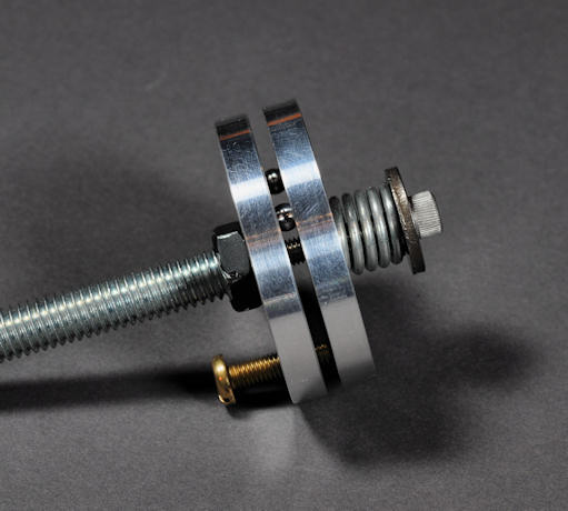
The heart of the design consists of two aluminum plates, spring loaded together, pivoting on two ball bearings, and having a single adjustment screw for tilt. A secondary holder needs only tilt in the correct plane, and rotation, to achieve complete alignment.
You can attach the mirror to your holder two different ways, and you need to decide how before beginning the design. If you happen to have a common holder that uses a formed sheet metal shroud, the new holder can be sized to reuse it. You should make the holder plates the same diameter as the original holder, with the same tapped holes around the outside to attach the shroud. Lacking that, you can use an adhesive to attach the secondary directly to an angled tube. The latter method is generally reliable, but keep in mind that an adhesive failure could drop the secondary mirror right onto the primary mirror, probably destroying both. I've used the adhesive method, even with a very large secondary, with no problem. The adhesive method allows the secondary to be offset slightly, if you wish to include that admittedly small refinement in your design.
Fabricate two circular aluminum plates a bit smaller than the obstruction diameter of the secondary. Other materials are possible, but the choice should be something that gives reliable adhesive bonds. Don't use an ungluable plastic! Both plates should be from the same material so the coefficients of thermal expansion match. For most people 2" will be about right, though naturally a smaller secondary mirror will require a smaller holder. The thickness should be about 1/4". We'll assume your spider accommodates a 3/8" diameter threaded rod, but if you need something different change the following instructions accordingly.
Drill the center of both plates with the tap drill size for 3/8" x 16 (5/16"). Mark 3 points 120 degrees apart on a 1.5" bolt circle. This isn't terribly critical and you can draw it out on paper with a compass and protractor, attach the paper to the parts with double stick tape, then center punch the marks. Fasten the two plates together with a 5/16" bolt. You may wish to mark the mating faces, as they must remain the mating faces all the way to final assembly. IMPORTANT- you will drill through both plates in two locations only. The plates must be solidly fastened together for this operation. The third hole goes in the plate that will become the fixed plate. Do not drill the third hole in the other plate- the adjustable plate! The third hole is for the adjustment knob and it needs solid metal to push against. Tap the center hole of the fixed plate to receive the 3/8" x 16 rod. Tap the adjustment screw hole for a #10-32 screw.
The two plates pivot on two ball bearings that rest in the two holes described above. I used 3/16" bearings and 0.141" (9/64") holes. There is some freedom here, but if you change the bearing size, scale the holes by the same amount. Smaller bearings limit the angular adjustment and larger bearings waste space. Larger holes sink the bearings too deep. Smaller holes don't retain the bearings as well.
The secret to this design is that both holes were drilled at the same time and thus are accurately lined up with no extra effort on your part. After the holes are drilled, put a bearing on each hole, mate the plates together with the correct faces together and give them a moderate squeeze in your vise. This will create a narrow ring where the bearings contact, perfectly spaced, defining the pivot axis.
Drill and tap a #10-32 hole in the center of a 3/8" x 16 rod. We'll use that for a screw to retain the spring that holds the plates together. Cut the rod to the length needed to install in your scope.
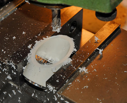
The angled mounting surface for the mirror is made from a piece of 2" PVC pipe. This can be cut with a hand saw, a table saw, a band saw, or set up on the milling machine. If sawing, use a good length of pipe against the mitre guide for safety and stability. If milling, be sure to make a plug for the inside of the tube or it will be impossible to keep it from slipping in the vise. No matter how carefully you think you've cut the angle, it's a good idea to check it with a gage or template to be sure. Small errors can be corrected by sanding- or ignored, since small errors can easily be accomodated with the normal adjustment range. Be sure the angled tube is long enough for the mirror to clear the screw and spring inside at the limits of adjustment.

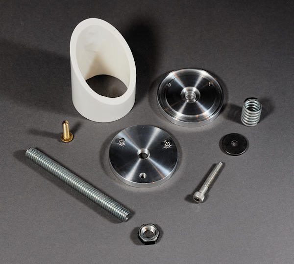
If you have a way to do it, cut a groove in the adjustable plate to better epoxy the angled tube in place. If you can't cut a groove, a few small screws through the plate and into the tube would be a good safety measure to augment the epoxy. A central counterbore to retain the spring is also nice, but not essential. You can see both these features in the photo below. The adjustment screw is just a brass #10x32 screw with the end rounded and polished. Naturally the more ambitious can make a fancy knurled adjustment screw. A lock nut is also a reasonable addition. I don't like using any tools above the primary mirror so a knurled lock nut is to be preferred. Most of the rest of the parts are self explanatory and are shown below.

Here's how it all fits together.

There are several spring options. I used the compression spring for two reasons. The central bolt and washer insure that the two plates can't come apart. I also happened to have a suitable spring to cut a section from. You could use an extension spring pinned and buried in a hole in the 3/8" rod, but if the spring ever failed the secondary mirror would make a short, and likely very expensive, drop. You could also use a stack of Belleville washers as a compression spring. This would give high force and excellent stability, but travel would be limited. Belleville washers also tend to be harder to get and quite expensive. In any case, use a bit of thread locking compound on final assembly to insure that the screw doesn't move, as you won't be able to access it after the mirror is glued in place. The spring should be stout since good secondaries are thick. In the battle with gravity and vibration, you want the spring to win.
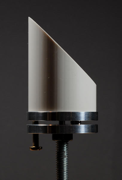
When you epoxy the tube to the assembly, put the adjustment screw on the high side as shown below. That way your hand won't be in the optical path when you align the scope. To get the rotational position right, put the face of the tube on the table and hole a thin ruler up against the ball bearings. With the ruler perfectly horizontal, make a small mark on the tube and adjustable plate. Align the marks when gluing the parts together.

My preferred epoxy is standard grey J.B. Weld to attach the pvc tube to the aluminum disk. The surfaces should be a bit rough and cleaned well. The secondary is attached to the pvc tube with clear RTV. Again, surfaces should be clean and the use of fresh adhesive is advised. Allow plenty of time for the adhesive to cure. Do not heat. I also removed the printing from the schedule 40 pvc pipe with some solvent.
PDF file of my secondary holder- modify as needed!
Enjoy.