An accurate voltage divider is often needed to calibrate test equipment and the Mini-Metrology Lab articles on this site show how to build a versatile Kelvin-Varley Divider (KVD). The KVD is in many ways the king of dividers, covering almost any arbitrary ratio, acting as an entire side of a bridge and having excellent accuracy. Unfortunately the construction of a KVD is time consuming and not for the faint-of-heart, plus it's overkill for many applications that just need simple 0.1X or 0.01X dividers, say calibrating the ranges of a DVM.
It isn't difficult, given a suitable bridge, or a high resolution DVM, to match resistors to near perfection. The downside is that the yield can be frustratingly low and building up high ratios will thus require starting with large numbers of stable close tolerance resistors, or possibly incorporating a trimming method. The end result can be expensive, overly complex, difficult to trim and potentially unstable. There may even be a loss of confidence in the ratio if the complexity is too great or the trimming too difficult.
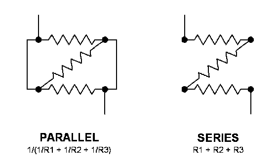
A remarkably elegant divider was worked out by B.V. Hamon in 1954 that solves many of these problems. Its construction is straightforward yet the details aren't as well known as might be expected. Practical construction information for the hobbyist is non-existent, though commercially the Hamon resistor is widely implemented. Fluke used Hamon's method in their model 752 divider to achieve sub part-per-million accuracy and many NIST calibrations and comparisons use the Hamon configuration. Hamon's method is based on his observation that slight matching errors in a set of resistors measured in parallel will largely cancel out when those same resistors are connected in series. The conversion of a parallel to series group of resistors makes possible an easy calibration based on equal values that results in a highly accurate divider of much greater ratio. That may be hard to visualize at this point but it should become clear when I describe the construction of the basic divider and how to adjust it.
Begin by choosing 3 resistors that are matched to a bit better than 100 parts-per-million. That's 0.01%, not nearly as difficult as for a KVD that might require 0.001% or better on the first decade. As a real world example I'll use the values from a Hamon resistor I recently built. I wanted a middle-of-the-road impedance so that strict 4-terminal construction wouldn't be needed. I also wanted the impedance to be low enough such that high impedance bench DVMs wouldn't load it. As often happens, the value choice was also determined by what was available in my junk box- a bag of 4.7K wirewound resistors. Three resistors were chosen that measured 4699.00, 4699.22 and 4699.21 ohms. That's well within the 100 parts-per-million window needed. The resistors were simply measured on a 6 1/2 digit DVM, though standard bridge methods would be as good or better. Remember, we only need a moderately good match, not a specific value.
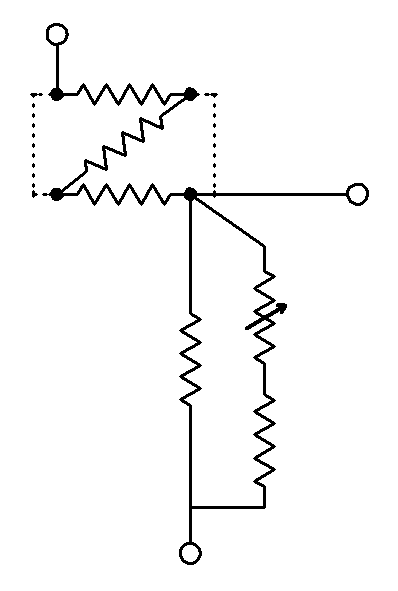
It's most convenient to wire up the divider using 5-way binding posts on a panel, matching the schematic view below below. The resistors are wired in a zig-zag manner such that they are normally in series, but can easily be placed in parallel by shorting two sets of binding posts with plugs or wires. Even a switch can be used if the contact resistance is very low.
Using our 4.7K resistor example, when they are all placed in parallel the new value will be 1566.38 ohms. The remaining resistor of the divider must be trimmable to exactly 1566.38 ohms. Typically one would use a slightly higher value, say 1.6K, shunted with a high value resistor and a low value pot. In my case this was 75K and a 1K trimpot. This arrangement preserves the stability of the main resistor and allows the value to be trimmed around the desired value by 1 or 2 ohms. This resistor assembly is placed in series with our previous 3 resistors and typically has one end grounded.
That's the entire 0.1X divider. To trim it the easy way, short the 3 resistors to put them in parallel and apply 2.000000 VDC across the divider. Measure across the trimmable resistor and adjust it for a reading of 1.000000 VDC (or half of whatever was applied). Measure across the top of the divider and confirm that it too has 1.000000 VDC across it. Fine tune the trimmer until the upper and lower sections have exactly the same voltage across them. The input voltage should be such that the output (0.5X) takes full advantage of a meter range, and it should be low enough to avoid heating the divider excessively. Do not allow the meter to change ranges (unlikely) as that brings its internal divider accuracy into play. If your resistors have good stability and a low temperature coefficient, 1-2 parts-per-million accuracy is achievable.
You can also use tried and true bridge techniques to match the top and bottom of the divider. I may add a complete description of bridge methods at some point, but if you're building this you probably already know how to compare two identical resistors.
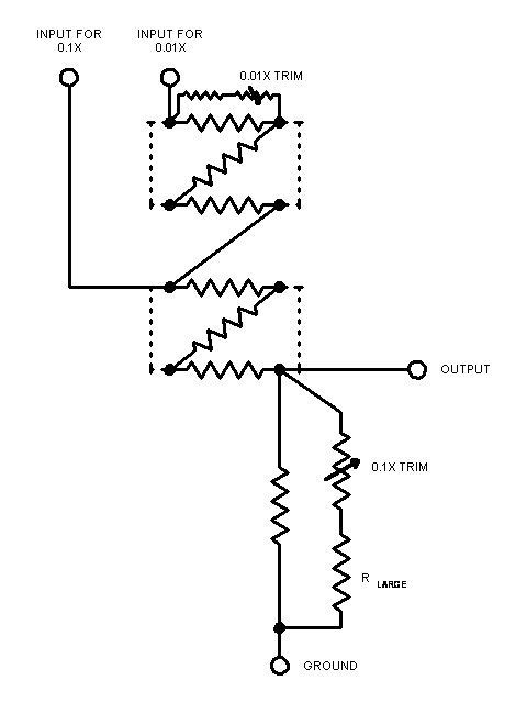
Finally, remove the shorting plugs or wires to change the divider from 0.5X to 0.1X. The voltage pickoff point remains the same. To add the 0.01X range, 3 more resistors are used in exactly the same way as previously. These 3 resistors, located above the previous 3, when placed in parallel with shorting plugs or wires, will exactly equal the resistance of the rest of the divider. Using our example, the divider has a total series resistance of 4699.00 + 4699.22 + 4699.21 + 1566.38 ohms (15663.81).
The next group of resistors will thus consist of 3 resistors, each being 3 x 15663.81 ohms (46991.43 ohms, about 10X the original divider values). Again, they should be selected to match within 0.01%. One of the three resistors should be selected slightly high so a trimming network can be placed across it. The trimming procedure is the same as the first; apply shorting plugs or wires to place the new resistor group in parallel. Trim the one trimmable resistor in the group for exactly half voltage between the group and the rest of the divider. This section can be tricky as the resistors need to be close to the optimal value such that one can be sufficiently trimmed while keeping within the 100 parts-per-million matching requirement. Remove the shorts and the original pick-off point will now be a 0.01X pick-off.
This has been a somewhat abbreviated write-up, as I've omitted discussing resistor stability, lead compensation and best wiring wiring practices to avoid voltage drops in the divider. Good sources for more information include the Mini-Metrology articles on this site, the Fluke book "Calibration: Philosophy in Practice" and the instruction manual for the ESI SR1010 (or 1030/1060) resistance transfer standard. This divider should be constructed in a similar fashion as the ESI units, which can also be used as Hamon resistors. You may also want to make up a simple Excel spreadsheet for the divider to show how errors in the groups of 3 resistors affect the final division. This is also useful if you want to create other ratios by using more resistors in parallel or more groups.
Conrad R. Hoffman
5/6/2010