Many people feel that different interconnects have different sonic characteristics. The belief is strong enough that suppliers and customers exist for interconnects costing upwards of hundreds of dollars a foot.
Blind tests, whatever they may or may not reveal, offer little design guidance. Simple math shows that interconnects with reasonably low capacitance won't affect system response enough to matter. Specifically, with a source impedance of 1000 ohms, high for all but passive preamps, infinite load impedance, and a typical 200 pF interconnect, the response would be 3 dB down at 795 kHz. That's 0.003 dB down at 20 kHz, certainly not audible in any way shape or form.
Move along folks, nothing to see here.
It would be great to leave it at that, but the fact remains that even I, rejector of subjectivism, am convinced that different interconnects do not sound the same. I've witnessed it first hand. I am, however, willing to change my opinion, given enough evidence, so be sure to read all the way to the end.
Making yet more capacitance measurements isn't going to lead us to the truth. The math is clear on that. What's needed is a test that can show up signal differences at mid audio frequencies with similar impedances to what you'd find in a normal system.
One of the most powerful tests for audio differences is a two-path measurement, with a differential amplifier used to subtract the two paths. If any difference exists, it can be amplified for observation. Any test signal can be used, including music, if you believe that lab test signals don't tell the whole story. One of the really nice things about differential measurements is that you don't have to understand or have a name for the error. Once the error is seen, the root causes can be sorted out later.
The test setup turns out to be very simple. We can just drive the two inputs of a differential amplifier through resistors, simulating the output impedance of a preamp, and hang the various interconnects off one input to see the degradation of the signal.
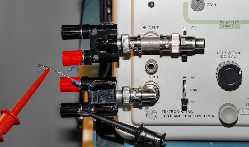
Sometimes old and modest equipment is better suited for analog audio measurements than anything else, or at least cheaper. The test is shown below using a Tektronix 545B scope and 1A7A differential plug-in, though there are certainly lots of different ways to accomplish it, including using two channels of a PC sound card.

You can see the signal being brought in from a function generator and applied equally to the two inputs by two 1 kohm resistors. In a perfect world the resistors would be identical and the two input channels would match exactly. It's not a perfect world, but with a 12 volt peak-to-peak triangle wave applied, the signals are pretty well cancelled as shown here at 5 mV per division.
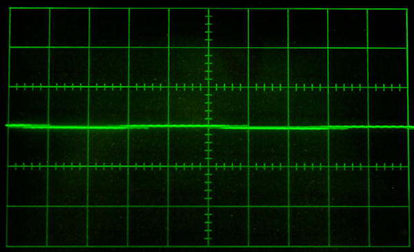
The test is sensitive enough to see the addition of a single RCA-to-BNC adapter.
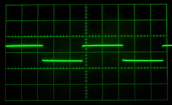
The worst interconnect in my collection is about 255 pF, so we'll start by checking the setup with a 270 pF silver-mica capacitor of good characteristics, rather than an interconnect. The capacitor should be a more perfect capacitance than most interconnects and will show us what the ideal waveform should look like. Driving the system with a 2 kHz triangle waveform, the capacitor will change the phase slightly on one channel as it charges and discharges on the rise and fall of the triangle wave. Subtracting the two channels should result in a reasonably good square wave, something easy to evaluate and the very reason for choosing a triangle as the input signal. This is shown below.
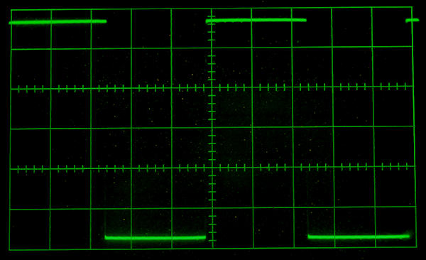
The amplitude is small, only 27 mV peak to peak, compared to the input of 12 V peak to peak, but the result is exactly as expected. The amplitude of the square wave is entirely dependent on the value of the capacitance attached to either of the inputs, and the shape will be a perfect square wave for a pure capacitance. But, we've already concluded that capacitance is not the parameter of interest with interconnects, so what else can this test tell us?
It's typical, or at least it used to be, to receive "free" interconnects with the purchase of new audio equipment. Over the years they tend to multiply and even get used occasionally. I have one in particular that I felt didn't sound very good, a sonic meadow muffin at best. Let's plug it into the test setup.
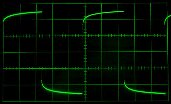
Now we're getting somewhere. What you're seeing is the difference between the signal that's supposed to be there, the unloaded scope input, and the signal that actually showed up, the input with the cable attached. The cable capacitance is responsible for the height of the square wave, but some other factor causes the rolled off shape. Note that this is only a 2 kHz test, so that rolled off portion is right smack dab in the middle of the audio band, contrary to many explanations for cable sound that only come into play at RF frequencies.
Can you hear it? Well, I've always thought this cable sounded dead and lifeless. Another round of listening tests with a friend confirmed that the character of the high frequencies was softer and the system resolution was lower with this cable. It was not the life changing night and day difference that audiophiles often ascribe to differences, but it was obvious and unmistakable even to an untrained ear. It made the difference between the music being emotionally engaging and not. Changing the cable to almost anything else seemed to be an improvement. By the numbers, that droop is about 5 mV peak, compared to the 6 V peak input signal. That's .005/6 or 0.00083 or 0.083%. A tenth of a percent doesn't seem like it should be audible, but maybe there's something else going on.
Looking for more confirmation, I had another friend over, an experienced musician. He too confirmed that there was a difference, though he thought the soundstage was actually better with the "bad" cable. Now, that was a bit bothersome for an effect that I knew to be easily heard.
Here's another freebie cable, visually the same as the first, but apparently they ran out of the really horrible dielectric material and had to use something else.
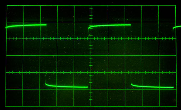
Next we'll do a piece of microphone cable. This is Belden 8420 and I was surprised that it wasn't better, though the capacitance is quite low as shown by the small amplitude of the square wave.
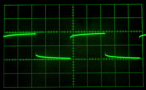
A common cable with very low capacitance is RG-62 coax. It's a bit stiff but makes a reasonably good interconnect if you don't have to bend it too tightly. Let's see how it does in this test.
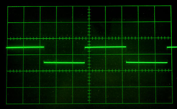
Pretty good stuff. Low capacitance as shown by the low amplitude of the square wave, and almost no distortion of the shape.
Here's the result from a vintage length of Monster M350. Capacitance is moderate but it's a good performer.
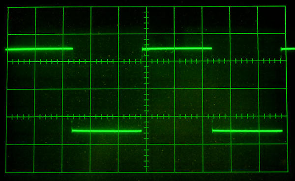
Finally, here's a length of twisted pair made up from some garden variety irradiated PVC hook-up wire, 22 ga., twisted about 22 turns/foot. The dielectric itself is pretty terrible, but as a twisted pair the capacitance is less then 9 pF per foot so any other effects will be kept to a minimum. This might explain the perceived good performance of various braided and twisted DIY interconnects. The dielectric performance would be even better if it were made with Teflon wire. The only caveat is that twisted pairs can pick up more hum and noise and won't be suited to some applications.
The most commonly measured capacitor parameter, besides value, is loss. This is the dissipation factor. It's sometimes expressed as ESR, though you may find power factor or other forms. One of the characteristics of loss is it's frequency dependent. Adding some artificial loss to the test capacitor using a resistor changes the rise and fall of the square wave, but doesn't duplicate the droop seen with the cables. The resistor isn't frequency sensitive like capacitor losses, but even varying it, the waveform never loses its flat topped characteristic. I'm not sure dissipation factor is the entire answer here.
So what else is there? Dielectric absorption. It's a time sensitive phenomena that can also explain the droop. Dielectric absorption is tied to dissipation factor, and sorting the two out separately can be difficult. There are only a couple standard tests for dielectric absorption, usually not in the frequency region we care about. Few material tables include it at all and they often don't specify the exact test method. As above, I'm not sure dielectric absorption is the entire answer here, but I'm willing to lump the losses together and call it a day.
Unfortunately, dielectric absorption is a bit of a pain to measure and there's no such thing as a dielectric absorption meter. In terms of design guidance, all is not lost. Though the relationship isn't absolute, it's rare for materials with low dissipation factor to have high dielectric absorption. A commonly mentioned exception is mica, and silver-mica capacitors tend to have high absorption in spite of their very low dissipation. Exactly how this comes into play isn't clear, as the silver mica capacitor used to test the system showed no evidence of a problem at our 2 kHz test frequency.
The capacitance of the cable also comes into play. The lower the capacitance, the lower any dissipation and absorption effects will be. Thus, if we choose cable materials with low dielectric constant for low capacitance, and low dissipation factor, it's unlikely we'll have any trouble with dielectric absorption.
Ideally one could create a single figure of merit for cables that that would take into account the capacitance per foot, the length of the cable, the dissipation factor and the dielectric absorption, to determine if any audible effects will occur. Maybe that can be the subject of a future web page.
This test is pretty good at showing if and how much a cable affects waveforms from a moderate source impedance. The lower the source impedance, the less effect a given cable can have. A very low source impedance preamp driving a typical solid state power amp is not going to be very sensitive to what cables are used to connect them. On the other hand, a high output impedance source will certainly be more cable sensitive. Many tube preamps, some solid state preamps (Dynaco PAT-4 as an example) and CD players with output muting transistors and current limiting resistors at the end of the signal chain, fall into that category.
The question still remains, can you hear it? To really answer that, a proper double blind test (DBT) would have to be conducted. That's quite difficult to do properly, so I decided to do something to make the cable difference as pronounced as possible. I constructed a small switch board that simply allowed the "bad" cable to be instantly connected to the system while playing test tones or music. The signal doesn't actually have to pass through the cable in question, so simply connecting or disconnecting it to short low loss cables between the components should be audible if the "bad" cable losses are really a factor. I figured if the "bad" cable was switched in and out while playing a pink noise signal, any subtle change in tonal balance would be instantly obvious.
Drum roll please. Under no circumstances, with music or with test tones and noise signals, with speakers or head phones, did any cable sound any different than any other cable. At the instant of switching, nothing changed. The low end was the same, the midrange was the same and the high end was the same. And this result was with a system that, by the numbers, should be quite sensitive to cables. It just doesn't matter. Maybe there's some cable that's so long or has such a bad dielectric that a difference could be heard, but based on these tests you'd have to work pretty hard to find it.
The thing that caused me to explore this was in fact a CD player that I found deficient in sound quality. It turned out to have a surprisingly high output impedance, and changing cables seemed to make an obvious difference in the sound. The problem is audio memory is lousy and listening biases can convince us of many things. Things that ain't necessarily true.
Now, all this said, there are many cables with reasonable capacitance and negligible dielectric absorption. You don't even have to pay a lot of money for them. I now firmly believe that those cables will all be indistinguishable in a blind listening test. Based on the above tests it would be completely unexpected if a difference could be heard. Given a choice, I'll still stick with short low loss cables just on good engineering principle, but it makes no sense to spend an extra dime on exotic or boutique cables, or to believe any claims of superior performance. Buy cables for the mechanical quality of the connectors, the shielding and a good price. If you like the color, so much the better.
C. Hoffman
last edit August 13, 2014