There are people with decades of grinding experience, who do great work, who will tell you they've never balanced a grinding wheel in their life. My guess is they have heavy high quality grinders like a Brown & Sharpe 818 Micromaster or bigger. The heavier and more rigid the grinder, the less susceptible it will be to vibration caused by out-of-balance wheels.
Then there's me. And maybe you. I got my Boyer Schultz 612 Challenger for $100. I like to joke that I bought the magnetic chuck for $100 and the fellow was nice enough to throw in the grinder for free. I did have to rebuild the spindle and tune it up a bit, but it's a great grinder for the home shop. I put a VFD on it, both to get the necessary 3-phase and to have control over the wheel speed. It's pretty similar to the small Harig and other 6 x 12 grinders. My guess is they all benefit from well balanced wheels.
I hear you saying, "But I don't really have a problem." I'm speculating, but here's what I think happens. An out-of-balance wheel sets up a vibration in the machine. That vibration is in phase with the rotation of the wheel. When you dress the wheel it actually comes out slightly out of round, compensating for the vibration under the specific conditions during the dressing operation. As long as conditions remain the same in terms of wheel speed and structure (how high the head is, mass on the chuck, leveling etc.) the wheel will grind a fairly decent surface finish. On the surface (no pun intended) you really don't have a problem.
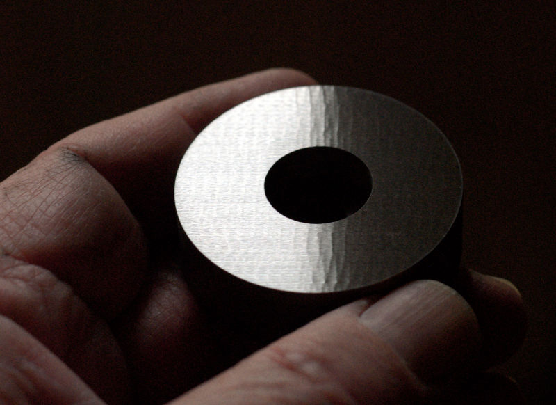
Here's what I hope is proof of the theory. First, I left my white wheel out-of-balance, dressed it and ground some steel. The surface was very good. I could see some slight, and I mean very slight, waves due to the out-of-balance condition, but most people would be perfectly happy with it. I couldn't photograph the slight waves because they only show up under the right light and then only when the part is tilted back and forth. Next, I carefully balanced my white wheel and dressed it. As expected, it ground beautiful near-perfect surfaces. Finally, I removed the balance weights, did nothing else, and ground the surface again. Here's the result.
Note that it's hard to get consistent photos of grinder surface finishes, as the type of lighting can make the best look bad and the worst look good. I've lit the surface to show the pattern as clearly as possible.

Pretty awful, eh? So what does this mean? It means that the geometry of the wheel is different, depending on how much it's vibrating when dressed.
Now, you might get lucky and buy wheels with inherently good balance. Maybe you only buy 1/4" wide wheels, which are usually well balanced by virtue of their low mass. Luck has never been with me. I bought an expensive Norton SG wheel that wasn't well balanced. I recently bought an inexpensive CGW white wheel that was no better.
If careful dressing of an unbalanced wheel solves the problem, why worry about balance? First, you won't get the best surface finish the wheel is capable of. Second, anything that changes the wheel speed or the dynamics of the mechanical loop between wheel and part, could bring on the ripples of imbalance unless you redress for the new conditions; the quality of heavier cuts should be better. Lastly, it's probably better for the spindle bearings to carry a balanced load.
In theory, balancing is as simple as can be. Just find the heavy spot and remove material until the assembly is balanced, or add material opposite the heavy spot until the assembly is balanced. There are various ways to go about it, from something as simple as putting an axle through the wheel and resting it on parallel rails, to fully automatic balancing systems built into the grinder. I'm going to show you how I do it, using a 4-pass balancing technique with an accelerometer. We'll break the problem down into two parts. First, we need a way to measure the amount that the wheel is out-of-balance. Second, we need a mechanically acceptable way to correct it.
An out-of-balance wheel creates vibration and that's what we're going to measure. The tool of choice is an accelerometer. They used to be expensive (some still are) but now you can get an accelerometer in a chip, made with MEMS technology. A 3-axis device on a small circuit board can be had for about $10 to $20. Look for ADXL337 or ADXL335 from Sparkfun Electronics. There are also many industrial accelerometers made by places like PCB Piezotronics that show up on eBay. Do your research carefully as you want a sensitive device with an output you can deal with. That might be analog (for me), USB or something else. If you're handy with a soldering iron, the $10 solution is for you. If not, something more turn-key will be needed. I use a surplus Wilcoxon sensor that was made for very low frequencies, but it also works well for machine tools. Most accelerometers need some type of downstream amplifier and filter. I can't tell you exactly what you need or how much to spend, as it depends entirely on your skill level and ability to scrounge things.
Some phones have built in accelerometers. There are vibration analysis apps, some for free, that should do the trick. Not being a phone geek, you're on your own with this one too, but it might be the fastest and easiest way to get the job done.
It's important to know the frequency of the vibration. RPM divided by 60 gives you RPS, which is also going to be the frequency in Hz. Most small grinders run at 3600 RPM. 3600/60 = 60 Hz. It will be necessary to filter out everything other than the 60 Hz signal for good results. That means you need a filter, which can be a small opamp circuit after the accelerometer, or possibly a filter built into the amplifier/meter system.
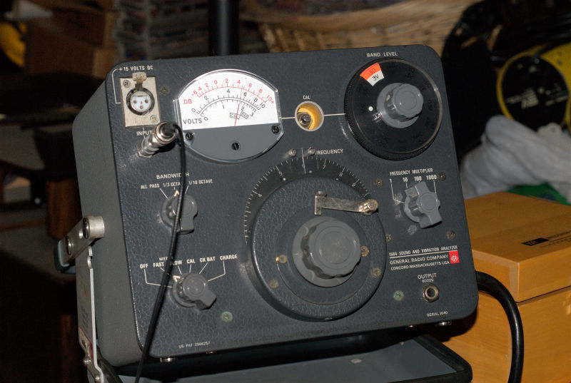
I use a surplus Wilcoxon seismic accelerometer, its matching amplifier and an old General Radio 1564 vibration analyzer. That's nothing more than an amplifier with a filter and a meter to read out the amplitude of the vibration. Note that I have it set to 60 Hz (6 on the X10 range). If you have something with a spectrum analyzer display, like a phone, just pay attention to the level of the 60 Hz peak. Here are some pictures of my setup, which will likely look nothing like yours.
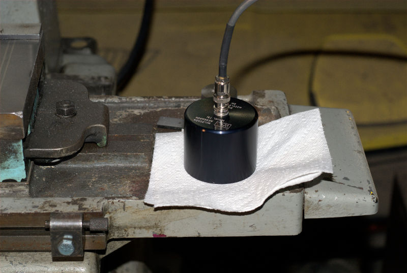
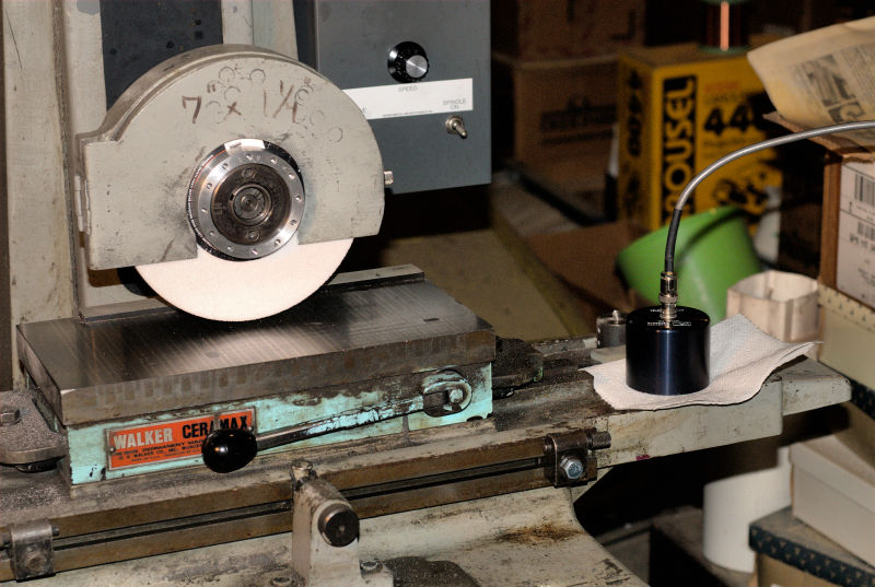
The obvious place to put the accelerometer is on the spindle assembly. It turns out the location isn't important, and you should put the device wherever you feel significant vibration. On my machine, the table next to the chuck works fine. Just rest your fingers lightly on various parts of the machine and use whatever spot is convenient. The reason this works is because the 4-pass method relies solely on the amplitude of vibration. As long as changes in balance make things better or worse, it will give you an accurate result.
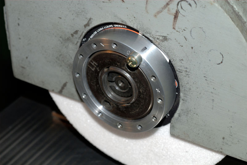
Some wheel adapters have provision for adding balance weights, or have weights that can be moved around a track. I had neither, so made an add-on to accept screws and washers as weights.
Before continuing, I want to cover a few important safety items. Grinding is generally safe as long as wheel integrity isn't compromised. A cracked wheel can lead to disaster if it comes apart at speed. Before mounting a wheel you need to gently ring it like a bell. It should produce a clear tone, not a dull thunk. Support it by the center and tap the face with the plastic handle of a screwdriver or something similar. Here's an MP3 file of what it should sound like.
If you have a bad wheel, hold it over the trash barrel and smash it with a hammer so it can never hurt anybody! You don't want some idiot to mount it up and have an entirely avoidable accident. Caveat- there may be wheel types that don't ring strongly, but I've never run across one.
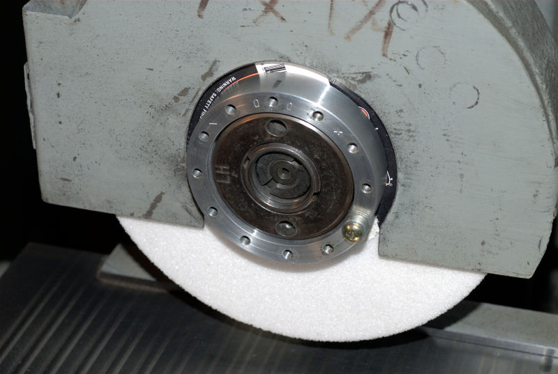
Next, the wheel must have heavy paper rings (blotter paper is often cited) where the clamping surfaces contact. It is absolutely critical that the clamping faces match up on ID and OD. Mismatched clamping surfaces will apply shearing forces to the wheel and likely crack it. Think about a Greenlee punch. That's exactly the situation you don't want. You want the wheel held in compression, not shear. Here are photos of the back of my wheel adapter, the new balancing ring and the fastening nut.
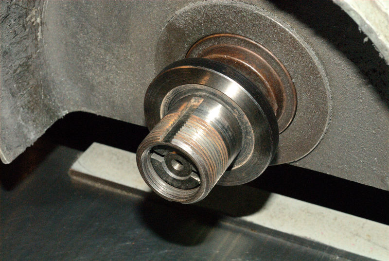
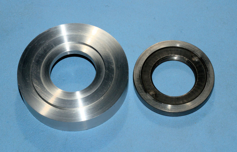
Note that the contact areas of the adapter match the nut and the back of the wheel adapter shown earlier. Again, this is extremely important for safety.
The balancing adapter mounts under the fastening nut. Your adapter will likely look different, depending on clearances to the wheel guard. Note that I've stamped around the zero degree hole and added plus and minus to either side so I can remember which is which.
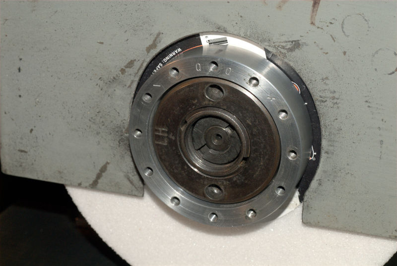
We're going to do what's known as a 4-pass balance run. It's really quite simple, though it does require writing down four numbers, something I seem to mess up about half the time. What we do is power up the grinder and dress the wheel. It will likely be out of balance. We take the first reading from the accelerometer.
Next, we take an arbitrary small weight, say 3 grams or so, and attach it at the zero hole of the adapter. Again we power up the grinder and record the accelerometer reading. It's critical that we run the grinder at the same speed and not disturb the location of the accelerometer or anything else.
The third step is to move the weight in the positive direction by some amount. I like 120 degrees. Power up and record the reading.
The fourth and last step is to move the weight by exactly the same amount to the negative side, -120 degrees in this case. Power up and record the reading.
Now you have four vibration amplitudes. You also need the mass of the test weight. Small digital scales are as common as dirt these days, but I still use my old-school triple beam.
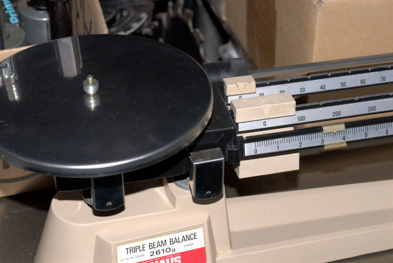
The balance calculation is a bit of a pain to do manually, so I've made a spreadsheet you can download. As an example, I did the 4-pass runs on my CGW wheel and got 2.3 volts, 0.95 volts, 2.43 volts and 2.8 volts. The mass of the test weight was 3.5 grams. Note that the units are not important, so long as you stick to one system. If you had a laser pointer bouncing off a mirror on the grinder, you could enter how many thousandths of an inch the beam moved on the wall. The mass can be pounds or milligrams, so long as you stick to the same units when determining the final balance weight. Here's a screenshot of the spreadsheet for the above data.
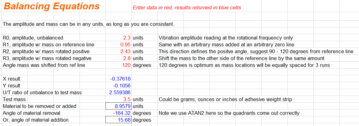
The result is that we need to add 8.96 grams at +15.68 degrees to balance the wheel. We don't have a handy hole there, so the spreadsheet also has a section to calculate split weights where we do have holes. Usually I just get as close as I can, than do another 4-pass run to fine tune it. It's a good idea to do a second run anyway, unless you feel absolutely no vibration on the handles of the machine as it spins up.
Here's a photo of my end result. It's a surprising amount of weight for a 7" wheel. I don't really like using a washer so large that it hangs out over the edge of the balancing adapter, but that's how much weight was needed.
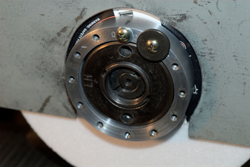
Admittedly, my balance adapter is a bit inelegant. The weights should be closer to the plane of the wheel and the whole thing should really be integral to the nut, but it works quite well. Just be careful if you do grinder setups with V-blocks or such, that there's no chance of coming in contact with the spinning balance adapter or the screws and washers used for weights.
You can buy commercial wheel adapters with a groove and balance weights that clamp inside, but they're expensive. They also assume you're going to use an axle and parallel bars to balance, as the weights are on the inboard side of the adapter. You'd have to pull the adapter to use my method, though there's no reason it wouldn't work. A DIY adapter like mine could also be done with a groove in the front, and expandable weights that fit in the groove. Harder to make, but much more elegant. It could also just have an outer wall and use cut down adhesive lead wheel weight strips stuck to the ID. For the real McCoy, look at Wm. Sopko & Sons Co. under adapters and balancing.
Listening to the machine, you notice that in the unbalanced state there's a low pitched 60 Hz background hum. After balancing, the hum is almost entirely gone. Here's a soundclip with about 4 seconds of unbalanced machine, followed by 4 seconds after balancing.
The proof is in the pudding and here's that same test disc after a pass with a balanced wheel.
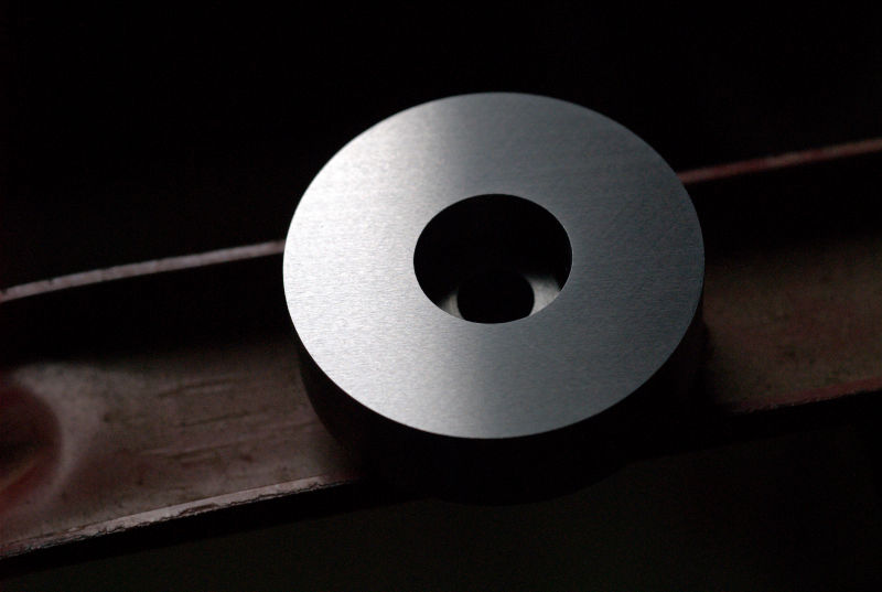
The surface has an Ra of 0.138 µm perpendicular to the grinding direction, not bad for a 46 grit wheel.
Long ago I was taught to dress a wheel slowly and with only a couple tenths downfeed at most. Maybe even a second pass at the same height. This is rubbish! Don't do it. A wheel dressed that way will cut poorly, generate excessive heat and risk burning the surface. You almost always want an open dress, done in a single pass of the diamond, quite quickly and with about 3-4 tenths downfeed. There will be times when something different is called for, but start there.
The part above, and most other parts I do, was ground with a 46 grit white wheel, coarsely dressed as described above. That's pretty coarse, yet the surface finish is just fine. If you need a better finish, go to a finer wheel, but rarely higher than 60 or 80 grit. The finer wheels are used mostly when you have to hold a sharp corner, not because you need a better finish.
In general, use harder wheels for softer materials and softer wheels for harder materials. I find wheel availability isn't as good today as it used to be, but you can find what you need if you search a bit and are willing to pay a slight premium. Unless you're doing production grinding, you probably don't need the premium ceramic wheels. Ceramic wheels may also require more force to perform well, something a small grinder isn't capable of. If possible, try before you buy and don't be surprised if you don't see a benefit over the inexpensive white wheels. It's also debatable whether ruby wheels offer anything that conventional white wheels don't, other than a pretty color.
Whenever you mount a new wheel, or remount an old one, make sure you dress it fully. Grind a piece of steel with some oil, then turn off the spindle and examine the wheel. It should show a trace of grey all the way around. If you see a light area for part of the rotation, you haven't dressed deep enough. That's the reason you should have more than one wheel hub, so you can change wheels without dressing off a huge amount on every change.
If your grinder is direct drive like mine, the speed is probably dead on. If you have a belt unit, it's not a bad idea to confirm the speed with a tach or strobe light. You never know if somebody messed with it in the past. I have some wheels that aren't rated to the full 3600 RPM, so it's handy to have the VFD so they can run at a safe speed. There are also times when you can do a better job with a little lower wheel speed, though that's often an indicator that the wheel isn't quite right for the job.
The VFD can also be set up to increase the motor speed, allowing you to maintain the SFPM at the wheel periphery as it wears, but I consider this too risky because somebody is apt to turn up the speed on a full size wheel.
I use Cool Tool II as a lube with steel, brushed on from the traditional tuna can. Never use the same can and brush you use at the lathe or mill. There will be metal chips that get pulled in on the climb pass of the grinding wheel, wreaking havoc with the surface of both part and wheel, also causing your heart to skip a beat when it happens. I also grind aluminum every now and then, for which WD-40 works well.
Here's an MP3 file of grinding the disc above. My spindle isn't as quiet as if it had new bearings. On some machines you'll just hear the air motion around the wheel. Still, it's the results that matter.
Finally, remember that this technique can be applied to balance just about any rotating device. We've done single-plane here, but 2-plane is also possible by mounting the accelerometer over each of the planes. I made a test stand and did my grinder motor that way.